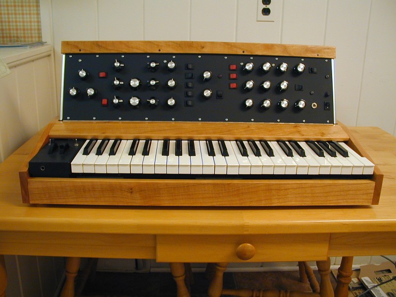
Building a Minimoog Model D Replica
In the spring of 2012 I started a project to build a replica of the Moog Minimoog Model D. I wanted mainly to learn about the design and get more familiar with this classic analog synthesizer. What better way to learn about a particular electronic thing than to build one? Also, I planned to add some of the the standard mods that people have developed over the years, and maybe even one or two of my own, and didn't want to hack up a "real" Minimoog to do that. I found several sites on the web concerned with DIY Minimoog projects, which gave me confidence. The idea of saving a little money along the way also appealed to me, although it took me lots of hours to save that money. My original estimate of parts costs was just a few hundred dollars, but I guessed by the time I got done it would be more like $500.
On this page I will show some photos of how things went and mention a few things I learned along the way.
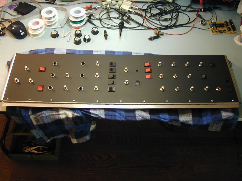
The photo at the top shows the more or less final result, unless I come up with a good way to add front panel labels.
Since there are no mechanical drawings or blueprints that I could find for the Model D, I started collecting photos from ebay listings back in April. Mostly they show the same things over and over, but every so often I would get a picture that would show a new detail and shed light on something that I had been trying to figure out. (The hinged bottom of the electronics assy, for instance) I made lots of measurements from these photos, by holding a ruler up to my LCD monitor, but also realized that there are a lot of distortions inherent in photography which limit the accuracy of this method. Luckily, I was able to make some size measurements on several Model D's. (Many thanks to Chris Hewitt and Logan Mitchell Sr)
I found a keyboard first, then found sources for and ordered all of the hard-to-get parts, so that I wouldn't get stuck at the end without some key component. Next I made and populated the PC boards, then made the front panel and the bottom piece of the electronics assy, mounted the connectors, mounted the controls, then wired up the controls and connectors. Then I made the top piece of the electronics assy, the cabinet, and finally the rear cover.
Keyboard/Keybed
Since Pratt-Read keyboards are not that readily available, and many of the ones that can be found do not have the required dual contacts, I decided early on to salvage a keybed from a more recent keyboard and adapt it. I bought a non-working Kurzweil K-1000 and cut down the keybed to 44 keys. Luckily, this keybed had several pcb's underneath with the key contacts and diodes on them and removing one board got me to exactly 44 keys. (It had three pcbs:32+32+12 for 76 keys total) The spacing of all the keys was the same, so when replacing the keys after cutting the metal chassis, I was able to start with an "F" key and end with a "C" even though the K-1000 had a different arrangement. The only issue is that the final C key was not designed to be the rightmost key, as visible in the photo. (The top K-1000 key was a G) The K-1000 used two rubber dome contacts per key to enable sensing velocity. I am currently only using one set of contacts, but may use the velocity information later. I designed a small pc bd that uses a PIC microcontroller to scan the keyboard and a DAC to generate the 1V/Oct signal needed by the Minimoog. A 10V trigger signal is also controlled by the PIC. Using the PIC and a scanned keyboard gets me several advantages. I was able to add a MIDI In port, so that either MIDI or the local keyboard can control the pitch. Since both sources use the same DAC, there is no issue with tuning the oscillators for one or the other, and no need to play a key on the Minimoog keyboard to use MIDI. Also, since this board can hold the voltage of the last key, I don't need to rely on the sample and hold of the Minimoog to not drift. (I modified the sample and hold so that it's always in "sample" mode) I put a second DAC on this board which is not yet used, but could be used to convert velocity info to a control voltage, or maybe for a dedicated LFO.
The Left Hand Controller assembly also came from the K-1000. Making one of these would have been a lot of work. I did have to replace the potentiometers with the correct values for the Minimoog. The Mod control is a 50K audio taper pot on the Minimoog, so that's what I bought. As I was installing it, I realized that it was facing the opposite direction from the pot in the Minimoog, so what I really needed was a reverse audio taper. Luckily, one of the other pots in the Minimoog is exactly that and I had bought a spare. I settled on mini toggle switches for the Glide and Decay functions. Since I didn't have the correct (white) rocker switches, the easier-to-mount toggles were compelling.
PC Boards
Luckily, the schematics for the Model D, and even some pcb layouts are available on the web. I decided to use the second version of the oscillator, as the components seemed to be easier to obtain, and most of the Model D's were shipped with this version. (I did substitute better (OP07) op amps on this board and also on the octave buffer to reduce tuning drift) I used downloaded (original) layouts for five of the six circuit boards. These were scaled using the size of known features, such as the 0.156" edge finger contact spacing. I laser-printed the foil patterns on overhead projector film, then exposed pre-sensitized pcb material through the film, developed it, and etched it. I did not attempt to plate any edge fingers with gold. Hopefully this will be okay long-term. I wanted to stay as close as possible to the original pcb layouts, so I used single-sided boards with jumpers, and tried to use as many of the original component types as possible. I used all original transistor types, except for the E402 dual JFET (replaced with LS3954A). (I resisted the temptation to spend lots of money on "tropical fish" capacitors, although I had one in my stock of parts, and found some others at no premium on the web, so I used them) I substituted multi-turn trimpots for the hard-to-find wirewound ones. I guess the wirewound ones are more stable with temperature, but the 25-turn ones are easy to adjust, and relatively inexpensive.
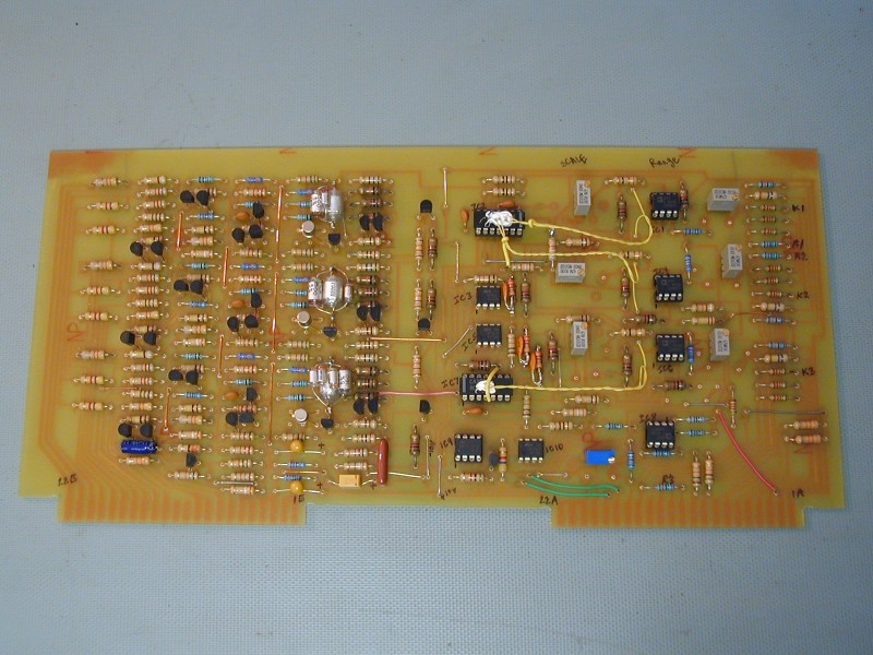
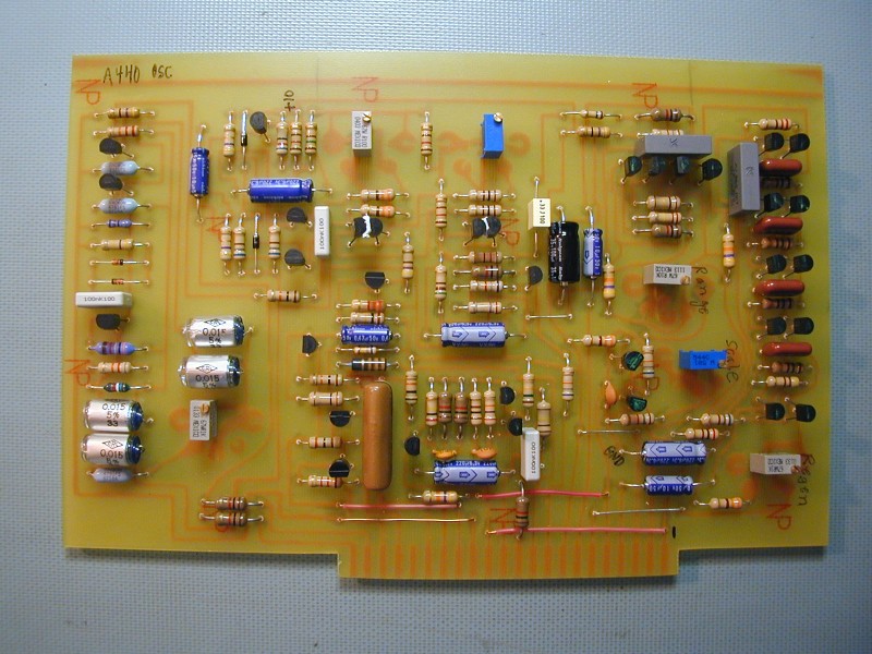
Here are some pictures of my pc boards:
Bd #1 Oscillator (3046 version), Bd #2 Contour, Bd #3 Pwr Supply, Bd #4 Filter, Bd #5 Rectifier and Bd #6 Octave Buffer
Front Panel
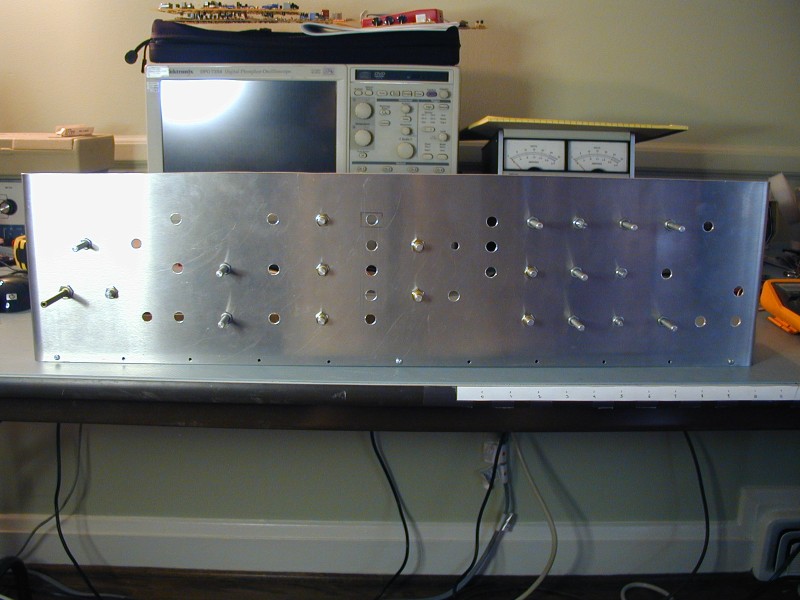
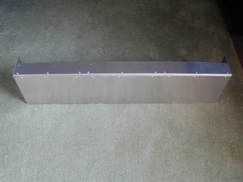
I got an inexpensive 30" bending brake from Harbor Freight and a nice big 36"x48" sheet of 5052 0.063" thick aluminum. This was about twice as much as I needed, but I thought I might need two tries at some of the pieces. I discovered that bending a 26" width of 0.063" aluminum is more than my brake can handle, so I have been working around that. Luckily, the front panel is only 7" high so bending the ends back was not a problem. I found all of the front panel potentiometers, including the #1 taper 5M pot, thanks to Google. I got the rotary switches on ebay (and wired up both halves in parallel for better reliability). I tried to find rocker switches that matched the Moog ones, but didn't have any luck. I settled on ones that snap into a rectangular hole. This worked out OK, but changes the look a bit. Also, I noticed after installing them that my switches snap as they are being flipped, unlike the Minimoog ones. Not easy to tell something like that from a web site description. I decided that $110 for the front panel press-on label was not in the budget. Since the rocker switches I used are different from the Moog ones, the press-on front panel label would not have really worked for me anyway. The Radio Shack knobs are pretty close to the smaller Moog knobs, at about 1/4 the price. I had one of the larger Cosmo knobs in my collection of parts, so buying a second one to match it seemed logical. The chicken-head knobs weren't too expensive and contribute a lot to the look of the front panel so I went for them. For the overload indicator, I used a superbright red LED. Just the current-limiting resistor had to be changed to make this work. I had a power indicator that was from about the right time period in my parts bin. Here is how the panel looked after I drilled holes for the controls, and here it is after painting, with all controls installed.
Electronics Enclosure
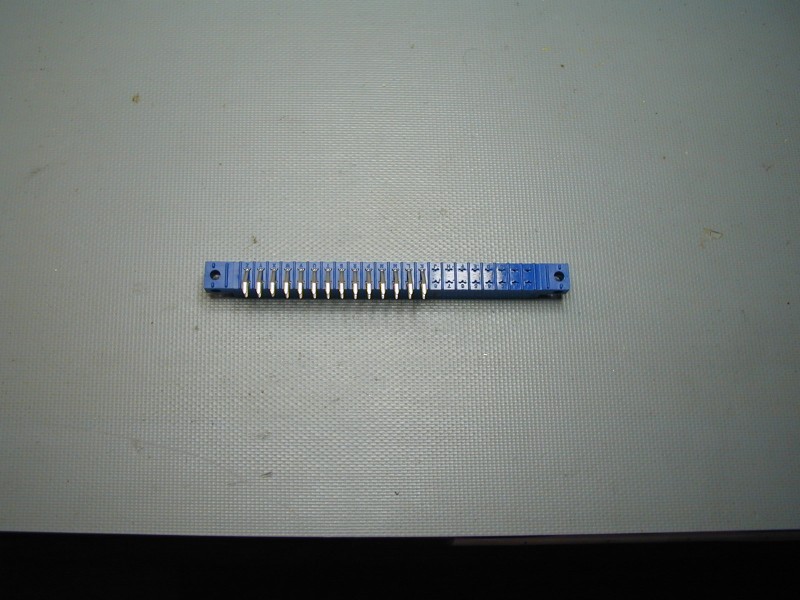
One problem which I faced was the unavailability of the Duo-Tyne connectors which Moog used for the four main pc boards. One did sell recently on ebay, but only one, and it was around $25. I needed six, so I decided to see if there was an alternative. I settled on a more std edge connector with the same pitch and number of contacts, but right angle pins. This allowed me to mount them just above the lower aluminum piece and only added about 1/8" of height relative to the Duo-Tyne ones. These connectors were available at no premium and have gold-plated contacts. Also, using them enabled attaching several wires to one connector pin, which I think is impossible with the Duo-Tyne ones. I was not able to find the shorter connector used for the contour board, so I cut down one of the longer ones after removing the extra edge finger contacts.
Once I had enough size information, I cut and bent an aluminum piece for the bottom of the enclosure. After mounting it to the front panel with a piano hinge, I laid my circuit boards in place on the back of the front panel to determine the correct placement. I tried to line up the edges of the boards and the connectors with specific controls on the front panel, so that they matched my photos. Also, the front two boards sit on standoffs which can only be located in-between the controls on the front panel, and I could see roughly where they belonged. I assumed that the standoffs were 1.25" long, and that gave me a rough idea of the spacing of the boards from front to back.
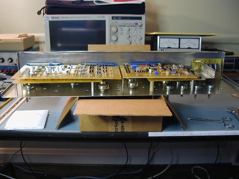
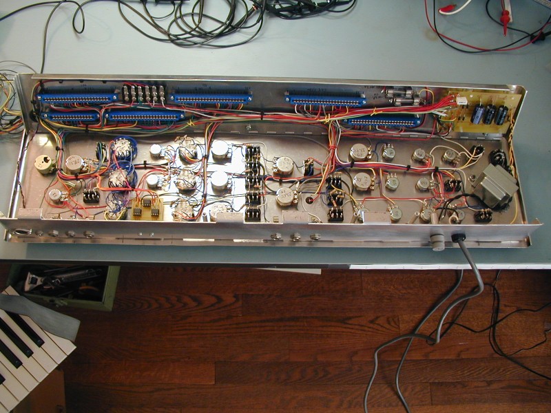
The rear pc boards are directly below the back of the top aluminum piece, so I made some more measurements and settled on a size for the top piece. I cut and bent another piece of aluminum and mounted it to the front panel, after mounting the 1/4" jacks, MIPI jack and the AC fuse holder (I decided to mount the two DC fuse holders inside, as I am hoping that these fuses will blow infrequently, and the internal mounting made the wires much shorter and was a lot easier besides) Since I wasn't able to bend a piece of aluminum the length of the top piece with my brake, I bent down metal tabs to hold it to the front panel and for the rear circuit board mtg. This leaves gaps along the back of the front panel but they're hidden by the wooden trim piece. I also mounted the power transformer at this point. Here is a photo.
The rear cover of the Minimoog is made from 0.050" thick aluminum, and has a bend across its entire width, which I was not able to make with my little brake using 0.063" aluminum. Also, most of them have welds along the joints between the sides and the top part, which I cannot do. My cover uses a separate piece for the top part, fastened with right angle pieces to the back. Here is how it looks. (I will cut holes for the trimmers soon)
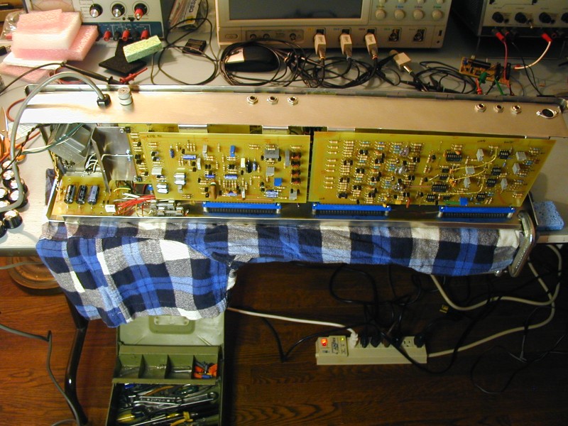
There is a lot of wiring for the pc bd edge connectors and the front panel controls. I decided to follow Moog's lead and use solid core wire (AWG 24) for this. Solid core wire is easier to work with, and should be fine where it doesn't need to bend often. I bought eight different colors of wire, 25 ft each, and tried to match the Moog colors when possible. They had all of my colors, plus those same colors mixed with white. I used yellow, for instance, where they had yellow and also where they had yellow plus white on the Moog. 25 ft was enough for all of the colors, and much more than I needed for some. I wanted to use stranded wire for the connections to the keyboard and LHC, since they need to flex when the panel is tilted up. In the next photo you can see a terminal block that makes the transition from solid wire to stranded wire for these connections. Here is a photo that shows how it looked after wiring the controls and connectors.
I tested the pc boards individually, without using the connectors, by applying power directly to component leads. This allowed me to get the power supply checked and adjusted, and also I found and fixed several pcb trace issues on the oscillator board and got all three oscillators working. Once these two boards were OK, I plugged them into the connectors, and then added the other two boards one at a time, measuring the power supply current as I went. I did not have any keyboard connected at this point, but was able to get the oscillators going, select different waveforms, try out the filter, etc. So far so good. Next I finished populating the S&H circuit and tested it out, then connected up the keyboard. (I had tested my PIC keybd interface months before when I first built it up and wrote the code) Nothing was tuned, but I could play keys and the pitch would change! This was a big deal to me, and I did nothing but play with the thing for about a week, adjusting the different trimpots to get the tuning and filter set up correctly. During this time I wired up the LHC and got that going.
The Cabinet
After a while I decided it was time to tackle the woodworking phase of the project. Luckily, my next door neighbor does some woodworking and I was able to get advice (and borrow some tools) from him. I bought a cherry board, after spending 20 minutes at the store trying to figure out if all of the pieces would fit. (I was expecting a standard size, but the boards they had were all different sizes and lengths.) The cut pieces needed to be planed to 5/8", and I had to modify the cabinet plans that I found on the web, as my keyboard and electronics module are not quite standard size.
On Time, Under Budget?
Well, not exactly. My original goal was to be finished with construction by Labor Day. I didn't quite make this deadline, although by that time I was working on the cabinet. As of Oct 11, I was pretty much finished, except for installing the oscillator hard sync mod, and drilling holes in the back cover from trimmer adjustment. My initial estimate of the parts costs did not include all of the little things that add up, like screws and bolts, rubber feet, piano hinges, polyurethane, boiled linseed oil, throw-away trays for PCB developing and etching, brackets for the cabinet, chicken-head knobs, a few resistors that I bought locally at a premium due to errors in the Moog parts lists, etc. At this point I have spent about $730, including the cost of the wood for the cabinet. Probably $100-150 of that was shipping and handling charges, as I had to get parts from all over the place, sometimes ordering just one thing. I also bought spares for the few parts that were hard to find . I used pretty much all new components, although a few were already in my parts bin. The line cord and power fuse had been saved from something years ago. I did buy a few things that I didn't use, such as the somewhat pricey male and female "Jones" connectors for the keyboard. I also ended up with a lot of extra 1/2W resistors, as it was sometimes cheaper to buy 10 when I only needed 4.
A small problem found and fixed:
After I became more adept at tuning the oscillators, I noticed that the instrument still sounded a little off. I could tune the oscillators correctly to certain notes on the keyboard (top and bottom A's) and other notes would be slightly off. I decided to investigate the voltage coming from my keyboard DAC and found that it was tracking key position correctly. Next I measured the difference between the input to the keybd track and hold circuit and its output. (I had wired it to always be in "track" mode.) I found that there was a small offset, which varied with the keyboard voltage. I suspect this may be due to improper matching of the two transistors in this circuit, although I followed the suggested procedure. Anyway, I decided to remove this circuit and feed my DAC output directly to the R-C glide circuit, then use a voltage follower, after the glide pot, to buffer the voltage before feeding it to the oscillators. I drilled 8 holes at the top of the contour/keybd pcb for a DIP op amp socket with an OP-07 in it. This cured the offset, and made things sound a lot better.
Some sound demos:
Not very musical. Just so you can hear some of the sounds.