IRMimic2™ Trainable IR Remote Control Transmitter with Macros

Features:
- Simple to train - Can learn up to 57 commands, and each can be in a different format/protocol
- Two different operating modes - Keypad or MCU interface
- Supports up to 32 keys in keypad mode
- Any key can be a macro (multiple command sequence) key
- LED indicator output - Indicates training is complete
- Chip operates from 3-5 volts DC
- Standby mode permits battery operation
- Can learn many different IR remote control protocols. Not limited to a few specific ones.
- In keypad mode, most commands are repeated if key is held down, except within macros.
- Kit w/pc board available for easy implementation. (All through-hole components for easy assembly.)
Add IR remote control of other equipment to your next project.
With IRMimic2, just apply power, train the chip with the IR remote control codes you want to generate, and you're ready to go. Code patterns are safely stored in internal non-volatile memory. The chip can be re-trained many times if needed.
IRMimic2 can learn up to 57 different commands, each in a different format, if needed.
In keypad mode, up to 32 PB switches, plus the "Learn" switch, can be connected. Each key controls a different command, or sequence of commands.
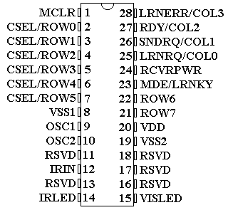
You can also control IRMimic2 with your favorite microcontroller, using MCU mode. Just provide 6 code select inputs, a learn input, and a send input. (Macros are not implemented in MCU mode, since they are not needed.)
Based on a 28-pin Microchip® PIC 18LF2420 CMOS microcontroller with EEPROM, IRMimic2 has been developed to work with most modern IR remote controls and accompanying equipment. It supports bi-phase, pulse width, and pulse position encoding techniques, as well as others.
Note: If you need 16 or fewer commands, and do not plan to use macros, or will be using MCU mode, IRMimic uses the same algorithm and should work exactly the same as IRMimic2. It uses a smaller PIC chip and a smaller PC board.
IRMimic2 Complete Kit:
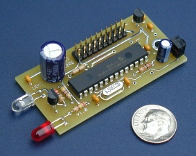
In addition to the IRMimic2 chip, we offer a parts kit, which includes a double-sided pc board and all components.
Kit includes IRMimic2 chip, on-board voltage regulator, 38 KHz IR sensor (works with most remotes, although several modulating frequencies are used), indicator LED, IR LED, 20-pin dual row header accepts ribbon cable connector for power, control signals. Regulator not required if 3-5V DC is available. Board dimensions: 1.25" x 2.5". Note: You will need to connect this board to either some switches, or to a microcontroller to complete your design. Please see sample application schematics.
Sample application schematics using IRM2 pc board:
This schematic shows how a keypad would be connected to the board.
This schematic shows an MCU being used for control.
This schematic shows how the board can be controlled in MCU mode with switches.
Here is some information related to powering IRMimic2 from batteries.
Here are several circuits (and a rather thorough analysis of them) for driving the IR LED with a constant current instead of a simple resistor, so that emitted IR intensity is relatively independent of battery discharge state. This material was sent to me by an IRMimic user.
Prices (not including small per-order S&H fee):
IRMimic2 Chip - $13.95 (programmed, with code protect bit set) Please download IRMimic2 chip data sheet. Also, please take
a look at the schematic for the IRM2 pc board and the sample application
schematics.
IRMimic2 pc board - $10.95 Please download IRMimic2 chip data sheet, IRMimic2 assembly instructions, IRMimic2 schematic diagram, IRMimic2 parts list, and IRMimic2 parts placement guide
Note: All parts needed to populate pc board, except the IRMimic2 chip, can be purchased at www.Digi-Key.com. The IR receivers and most of the parts can also be purchased at www.Mouser.com. Of course, the easiest way to get going is to purchase one of our complete kits:
IRMimic2 Complete Kit - $34.95 Includes IRMimic2 Chip, IRMimic2 pc board, and all components needed to populate board, 12" ribbon cable and female connector for IRMimic2 pc board end. Please download IRMimic2 chip data sheet, IRMimic2 assembly instructions, IRMimic2 schematic diagram, IRMimic2 parts list, and IRMimic2 parts placement guide. Note: You will need to connect this board to either some switches, or to a microcontroller to complete your design. Please see sample application schematics.
A word about compatibility:
IRMimic2 was designed to support as many different IR remote control command formats as possible. Some manufacturers use unusual operating frequencies, or formats that are simply not supported. IRMimic2 is not guaranteed to work with all remotes or equipment, but it should work with most of them. Here is some information on equipment that has been tested so far. Also, different remotes use different "modulation" frequencies. The above kit includes an IR receiver that is most sensitive to a modulation frequency of 38 KHz. All learned commands are transmitted using a modulation frequency of 37.8 KHz. This value was chosen to work with the widest range of equipment. If the original remote is operating at a different frequency, you will get reduced range/sensitivity.
DISCLAIMER: I take no responsibility whatsoever for the use and/or implementation thereof, or the misuse leading to damage to equipment, property, or life, caused by the above circuits.