Low Cost SP/DIF or AES3 Digital Audio Monitor/Level Meter
NOTE: I do not get enough inquiries about this to justify stocking the pc boards, chips and other parts. Here is a zip file with pictures of the pcb traces and the source code listings. It is all I can offer at this point.
Features:
- Automatically detects digital audio stream on either SP/DIF or AES3 (balanced) input jacks
- Displays sample rate, consumer/pro format, some errors, and the first five bytes of A or B channel status data
- Digital peak-reading level indicator for each channel
- Operates from a standard 9VDC wall adapter
- S/W tested with incoming sample rates up to 192 KHz
This is something that I designed recently for my own use during a consulting job. If you are interested in building something like this, please contact me. I would be willing to supply the PC board layout file and programmed PIC chips. You would need to supply the rest of the parts, using my parts list.
 This
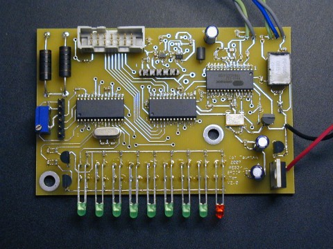
photo shows a fully populated Digital Audio Monitor pc board. Wires at top
connect to RCA jack for SP/DIF and XLR (balanced) professional digital audio
connector through small transformer at upper right. Red and black
wires are power connection. Dual-row connector is for standard
HD44780-based four-line LCD
module, with support for backlit type. (Potentiometer
adjusts LCD contrast) Two PIC chips are
used. One is dedicated to level meter function. Second PIC
reads status info and controls LCD module. Third chip is DIR
(digital audio receiver chip). Second row of LED's is directly
underneath the visible one.
This
photo shows a fully populated Digital Audio Monitor pc board. Wires at top
connect to RCA jack for SP/DIF and XLR (balanced) professional digital audio
connector through small transformer at upper right. Red and black
wires are power connection. Dual-row connector is for standard
HD44780-based four-line LCD
module, with support for backlit type. (Potentiometer
adjusts LCD contrast) Two PIC chips are
used. One is dedicated to level meter function. Second PIC
reads status info and controls LCD module. Third chip is DIR
(digital audio receiver chip). Second row of LED's is directly
underneath the visible one.
Here's how it looks in a simple aluminum enclosure:
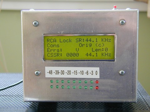 Top
line shows which jack is currently selected (SP/DIF) and the incoming
sample rate (44.1 KHz). Second line shows consumer mode status
format is being used, and that the "Orig" bit is set.
Third line shows that the "Valid" error bit is set. The
word length is 0, as my old CD player did not set these bits
properly. CSSR shows the channel status sample rate bits, in this
case all zeroes, which indicates 44.1 KHz. Top pushbutton can be
pressed to make the fourth line of the LCD display the first five bytes
of either the A or B channel status data. LED
level meter shows peak levels in dB, relative to 0dB.
Top
line shows which jack is currently selected (SP/DIF) and the incoming
sample rate (44.1 KHz). Second line shows consumer mode status
format is being used, and that the "Orig" bit is set.
Third line shows that the "Valid" error bit is set. The
word length is 0, as my old CD player did not set these bits
properly. CSSR shows the channel status sample rate bits, in this
case all zeroes, which indicates 44.1 KHz. Top pushbutton can be
pressed to make the fourth line of the LCD display the first five bytes
of either the A or B channel status data. LED
level meter shows peak levels in dB, relative to 0dB.
Here are the page1 and page 2 of the schematics and the parts list.
DISCLAIMER: I take no responsibility whatsoever for the use and/or implementation thereof, or the misuse leading to damage to equipment, property, or life, caused by the above circuits.