Z80 Microprocessor In-Circuit Emulator Design
I am no longer offering any parts, but all design files needed to build your own are here.
The pc boards can be purchased directly from Express PCB by downloading and installing their software (see below)
Note: Xilinx phased out the 5V CPLD that I used for this design in 2012. The 3V part WILL NOT work.
Some ebay sellers are still offering the 5V part. 10 or 15 nSec versions should be fine..
Designed to assist in debugging/repairing Z80-based computers, like those made in the 1970's or early 1980's. Inspired by Nicolet Paratronics' "NICE" Z80 In-Circuit Emulator, but with improved performance and additional features.
It can:
- Display and change Z80 internal registers
- Display, disassemble, substitute, fill, compare, and test memory
- Write to or read from I/O addresses
- Compute 16-bit checksum of memory region
- Trace through code with register display
- Trace through code (faster) without register display but with breakpoints
- Read or write Intel Hex file into/from memory
- Enable/disable interrupts or NMI to reach CPU
- Refresh system DRAM while Z80 is paused
- Look for EPROM or RAM in system under test
- Measure CPU clock frequency
It cannot:
- Run at full speed with breakpoints (This would require a lot more hardware.)
- Run at full speed and capture a trace of executed instructions. (same comment as above)
Features:
- Powered by system under test
- Z80 is socketed so different parts can be used
- PIC and HIN232 are socketed in case replacement becomes necessary
- Controlled by generic terminal program running on any PC/laptop with a legacy serial port
- Serial baud rate is automatically detected
- Tested so far in systems operating at 4 and 5 MHz. (Limited testing at 6 and 8 MHz) Briefly tested at 9 MHz. Above 8 MHz you are on your own.
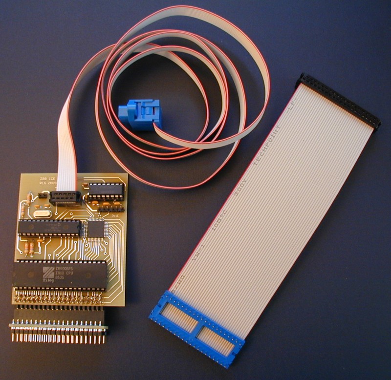
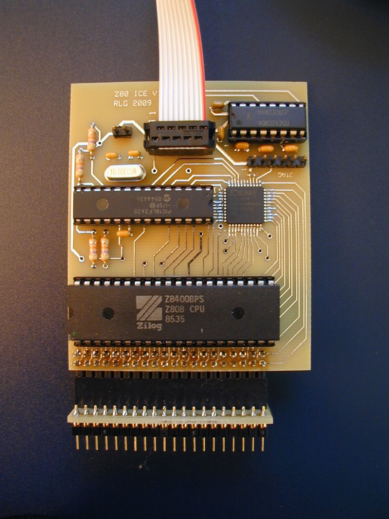
Above photo shows a populated Z80 ICE board with ribbon serial cable and 40-pin DIP plug attached. Using the DIP plug/socket provides the best connection to the target system, but may not always be possible. In those cases, the short ribbon cable (also shown) can be used. The four chips are: 6 MHz Z80B, PIC18LF2420, Xilinx XC9536 CPLD, and HIN232. PC board supports connector for ribbon serial cable or 6-pin header for USB-to-serial adapter.
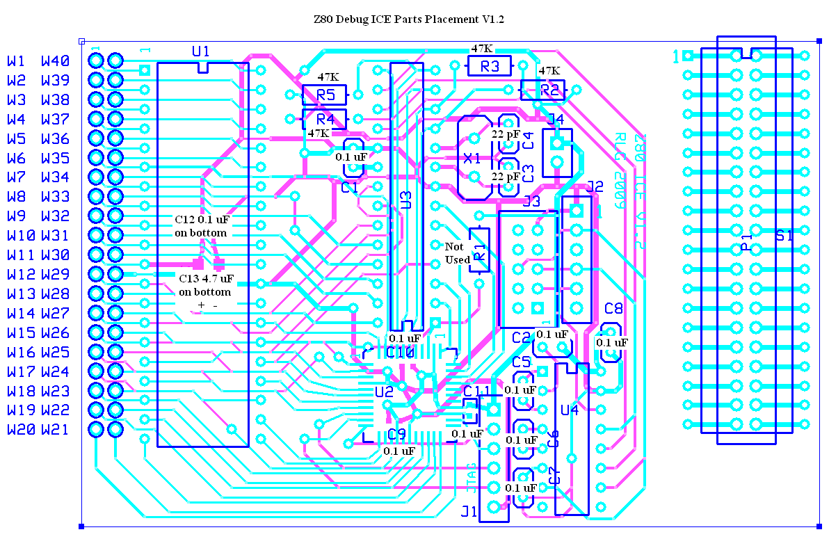
Here are the assembly instructions, schematic page 1 and page 2, parts list, parts placement, and operating instructions.
Note: Soldering the Xilinx CPLD used in this design requires a fine-tipped soldering iron and a steady hand. Please don't attempt it unless you have experience working with fine-pitch SMT parts. I won't be able to help you if your board doesn't work.
Note: To program the CPLD after it is installed, you will need access to some sort of Xilinx JTAG programmer. The one I use is an older design called "Parallel Cable III/DLC5". It connects to a PC's parallel port. (Here is a schematic, downloaded a long time ago from the Xilinx web site, which I think is for the JTAG programmer I have.) Clones of this may be available on a popular internet auction site. Also, although I haven't tested it, this site is selling a programmer that appears to use the same circuit as the Xilinx one that I use. Newer Xilinx JTAG programmers use USB and should work as well.
Note: You will need to program the PIC chip with some sort of programmer that can handle the PIC18LF2420. These programmers are available on a popular internet auction site. You will need a programmer that has a socket for the chip, not an in-circuit type, since my board does not have a header for in-circuit programming. I may offer programmed PIC chips if there is demand.
Note: I recently (6/2011) found several small issues involving V0.64 and older code: The disassembly of conditional call opcodes was incorrect. The number of instructions disassembled with the list command was sometimes less than requested. I also discovered that breakpoints were not working when using the trace command. (Untrace was OK) Several new versions of the code with these bugs fixed have been added to the .zip archive linked from this page. Nothing else was changed.
Here is a .zip archive which contains a .hex file containing the PIC code (my latest version, V0.72), an ExpressPCB .pcb file, and top.jed, which is a JEDEC file for programming the Xilinx CPLD using a JTAG programmer. The .pcb file is the correct size for the "miniboard" service, and contains the main board plus the 40-pin DIP plug. Cut the DIP plug PC board off before populating the main board.
Note: The pins on the DIP plug/socket are round machined pins, which may not fit into all IC sockets. Of course you could always plug the round pins into a standard IC socket which has flat pins.
Note: The design information offered here is not guaranteed to be useful for any purpose. Please download and use it at your own risk. I will not be able to help you get your ICE working if you have trouble.
Note about cabling: Someone recently built the ICE but put a male header on the DIP plug instead of the female, then was planning to use a female to female ribbon cable to connect this DIP plug to the ICE. This won't work, as it swaps the pins relative to what the standard female socket would do. Pin 1 of the ICE's Z80 ends up connected to pin 40 on the target system, pin 2 to pin 39, etc. Please stick with the DIP plug attached to the ribbon cable that Digi-Key sells and mount a std IDC female on it, as shown in the photo on this page. That will connect pin 1 to pin 1, 2 to 2, etc.
Watchdog Timers: Some people have asked about using the ICE in systems with watchdog timers that automatically reset the CPU if not written to. (Many arcade games and pinball machines use watchdog timers.) At present, the only way to do this would be to either add a small reset circuit on the ICE itself and disconnect the ICE from the target system's RESETb signal, or disable the watchdog timer on the target system. Luckily, some arcade games have a provision for disabling the watchdog timer. The ICE board has locations for on-board RC reset components. (You would need to add a diode in parallel with the pull-up resistor, and cut the reset trace to the target system to use this circuit. This connection should be cut between the Z80's RESETb pin and the target system's reset connection.)
DISCLAIMER: I take no responsibility whatsoever for the use and/or implementation thereof, or the misuse leading to damage to equipment, property, or life, caused by the above circuits.