EH Research Labs Model 4 NMOS EPROM Programmer
A trip down EPROM Memory Lane
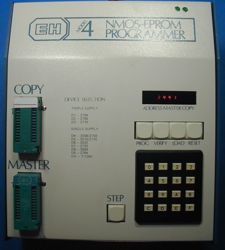
Someone contacted me recently about reading some 2708 EPROMs used in one of his vintage keyboards. This early EPROM requires three supply voltages: +5V, +12V, and -5V, and is only supported by a small number of (mostly vintage) programmers. Neither of my current programmers support it. I found a late 1970's programmer (EH Research Labs Model 4) on ebay that listed the 2708 on its front panel as being supported and decided to try my luck. It had missing LED display segments and I could find no info about it on the web. When I received the unit, I could tell that it was well made, but could not determine how to operate it. I was expecting to dump the EPROMs and figure out from the code how it worked. But as it turns out, this unit is based on a Signetics 2650 microprocessor, which I had never heard of. To make things more difficult, the two code EPROMs were TMS2716 types, which require three voltages to operate (like the 2708) so I had no way to read their data. Things were not looking good, but the unit was in good shape except for the display, and there was no obvious indication that it wasn't working.
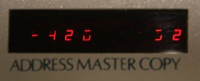
The original LED Display:
A little hard to read:
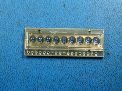
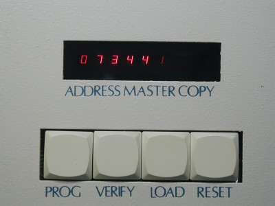
My first goal was to see if I could somehow fix the missing LED display segments. The display was a small 9-digit module with plastic magnifying lenses in front of each digit. This type of display was used in many LED pocket calculators in the 1970's, and I figured that an 8-digit calculator would need a 9-digit display to show a minus sign. Luckily, I had an old cheap LED calculator and its display module (made by HP) ended up being very similar to the one used in the EPROM programmer. The connector pinout was the same, so it seems there was a standard for this. I replaced the LED module with the one from the calculator, and now all of the segments were working. (Note that this is a multiplexed display, so getting a photo showing all of it at once is not so easy)
After more futile attempts to determine how to operate the programmer, I decided to try again to find a manual on the web. After changing my search a little, I found a manual for a similar unit (Model 1400) clearly made by EH Research Labs but sold under the MicroSupport brand. The manual had the complete list of commands and their usage, as well as complete schematic diagrams. The Model 1400 seems to be a later design, with more commands than the Model 4. The schematics were a little different as well, but the commands that were implemented in the Model 4 operated as explained in the manual. So now I was able to read a 2716 EPROM into the unit's RAM and dump the contents to the serial port as Intel Hex. But I couldn't figure out how to download data to the programmer, as this command was different in the Model 4.
I found that the MAME disassembler supports the 2650 CPU, and decided to try to dump the firmware EPROMs, mainly just to archive them, but also so that I could take a look at the code and figure out how to download data to the programmer. The Model 4 has two code EPROMs, a scratchpad RAM, and an internal EPROM data RAM buffer. Each of these has its own region in the CPU's address space. If I could map the code EPROMs into the data RAM buffer's space, then I could dump the firmware as Intel Hex using the command to dump RAM. So the next project was to draw out the memory address decoding circuitry. Turns out it is very similar to the Model 1400, which was a big help. Here is a schematic I created for the memory address decoder circuitry. (Use it at your own risk!)
With an extra IC socket between each firmware EPROM and its socket so that I could bend out the chip select pin, I used two schottky diodes and a 1K resistor to OR together the normal EPROM chip select and the one for the RAM buffer. The RAM buffer chips were removed so they wouldn't conflict with the EPROM on the data bus. Using this technique I dumped both of the code EPROMs twice to insure that I got the same data both times. The Model 4 has a third socket for an EPROM, but it's empty. The second EPROM is not full, so no reason to install the third chip. Here is an archive containing binary images for the two TMS2716 EPROM's used in the Model 4.
I converted the two firmware EPROM images from hex to binary and also combined them to make a single image for the MAME disassembler. Then I ran the file through the disassembler and spent some hours analyzing and commenting the code and trying to get familiar with S2650 assembly language. Here is an archive containing the code listing with some comments added. It is not valid assembler input, just something to look at. I figured out the sequence to download data into the programmer, which seems to work fine. (I did get a data error at 1200 baud, but 600 baud seems to work reliably) Serial cable only needs three wires: RX, TX, and Ground
I made up a cheat sheet that lists most of the commands used to operate the Model 4. Here it is.
The manual that I found on the web for the EH Research Labs/MicroSupport Model 1400 is too large to put here. The full name of the file is MicroSupport_Advant_PROM_Programmer_Series_1400_Instruction_Manual.pdf