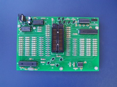
7400,74LS,74HC,74C and 4000 series Logic IC Tester
Note: I am no longer offering blank pcb's or programmed PIC chips for the tester. It is officially transitioning to a DIY project. If you want to order a pc board for yourself, please contact me and I will send you the Gerber files. The hex files for programming the PIC chips are already on this page for downloading.
Features:
- Tests most common 7400 series parts, some 4000 series parts, and a few SRAM chips
- Analog pin voltage measurement provides more information than simple logic test
- Input short or leakage test
- Interfaces to terminal or terminal emulator program via RS-232 (ribbon serial cable not shown)
- Auto-baud detect
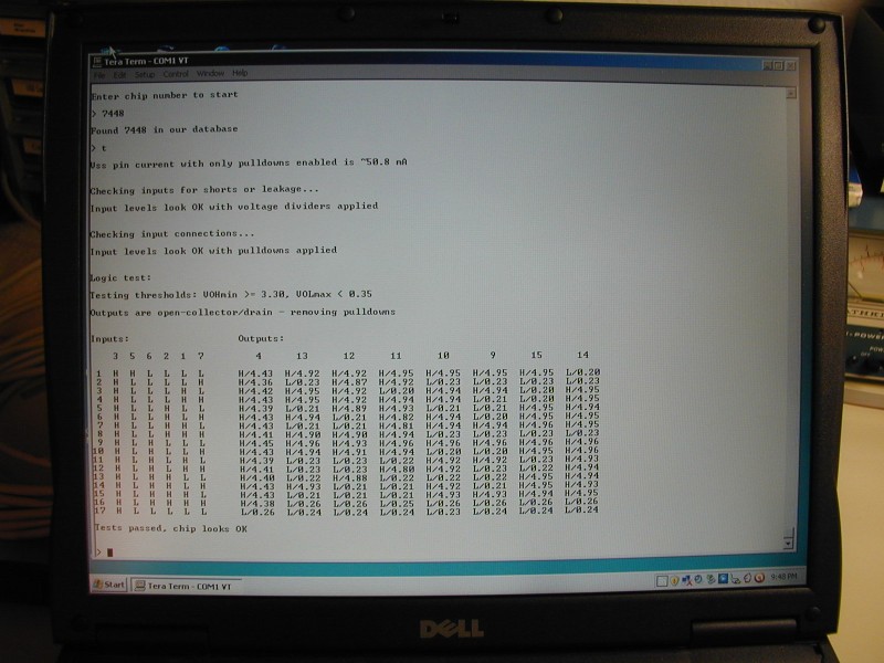
This picture shows how a 7448 chip test looks on a PC terminal emulator program:
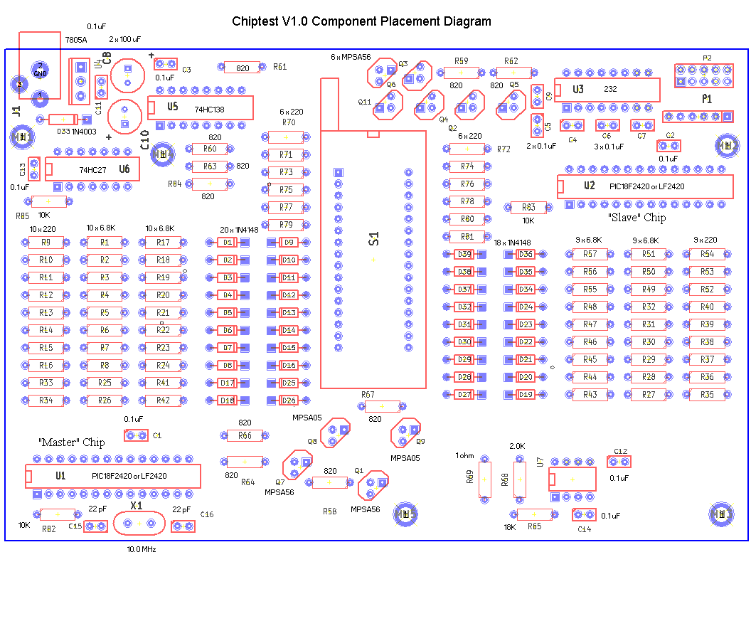
Most components are standard parts which can be obtained from several sources (see parts list). A 9VDC AC adaptor is also needed. PC board dimensions: 6.375" x 4.25". Before ordering, please download LogICtester user manual, LogICtester assembly instructions, LogICtester parts list. Version 1.2 schematic, component placement, and other info. Here is a list of supported devices.
Version 1.1 (not the current version) schematic and component placement.
Note: All additional parts needed to populate the pc board, can be purchased at www.DigiKey.com. Some parts are also available at www.Jameco.com and www.Mouser.com.
Below is a link to a shared cart that someone has created at Mouser for the IC tester (Thanks!). I have not checked this cart for correctness, so use it at your own risk. This cart was created based on the V1.1 pcb. For the V1.2 pcb, you would want to add two 10K 1/4W 5% resistors, a 330 ohm 1/4W 5% resistor, and a Green LED. Also, this cart includes the two PIC chips, which are included in the bare bones kit. You would only want to order these to have as spares, and you would have to program them.
https://www.mouser.com/ProjectManager/ProjectDetail.aspx?AccessID=ee63963503
Some small tweaks to the V1.2 pcb:
I made a few small changes to the pcb before re-ordering boards:
1) Unused section of the dual op amp is now tied off with two 10K resistors. (Not terminating this has not caused any problems in ten years of selling this kit, so please do not feel like you need to modify your V1.1 pcb. It's fine as is)
2) I added a spot for an optional Power LED (shows when the tester is powered, not the IC being tested)
3) I added two small jumpers for bypassing the RS-232 level converter IC.
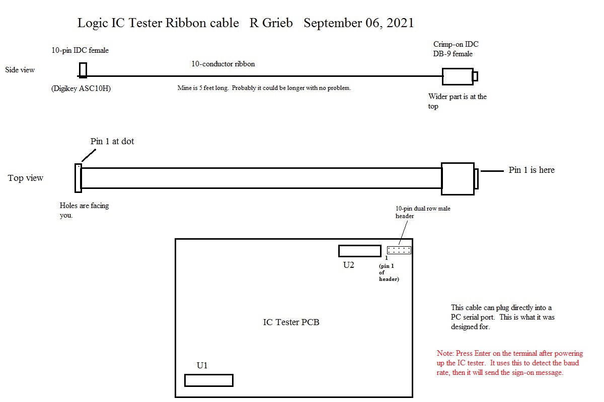
Here is a drawing of the ribbon cable that the tester was designed for. This will plug directly into the serial port of a PC. If you are using a different type of terminal, you will need to figure out a different cable connection. The tester only needs RX, TX, and ground.
RS-232 vs USB:
RS-232 serial communications was used before USB existed, as a way for devices to communicate. The voltage levels were much higher than what USB uses. Typically, a "1" level would be -12volts, and a "0" level would be +12 volts. USB uses 5V and 0V for these two levels. Logic chips and microprocessors operated with logic levels between 0 and 5 volts, so convertor chips were designed to convert the RS-232 cable signals to the lower logic IC levels, and also to convert the lower levels into RS-232 for transmission. The HIN232 or MAX232 chips are this kind of voltage converter chip. They convert -12V to a logic 1 and +12V to logic 0. Note that there is an inversion there as well as voltage translation. If the tester is used with some sort of USB adapter, you CANNOT use the MAX or HIN232 chip, as it will invert the signals. You don't need this chip anyway, as the USB adapter does not put out RS-232 voltage levels (+12 to -12). It puts out 0-5V or 0-3.3V signals. So these signals can be fed directly to the U1 chip with no level conversion and NO INVERSION. To do this, you would remove the HIN232 chip and bypass it. I have provided jumper pads on the V1.2 and 1.2a pcb for this purpose.
IC Tester Firmware
Here is the latest version (V0.60, created December 2022) of the chip tester firmware.
Here is the previous version (V0.59, created December 2021) of the chip tester firmware. Most modern EPROM programmers can also program PIC chips. All of the device information is contained in the Master (U1) chip, so there is no reason to update the slave chip U2 unless there is some problem with it. The hex files contain the code, and also the values for the configuration bits, which are stored in a separate area. Some programmers require this data to be entered manually before programming the device, and cannot read it from the hex file. If the configuration data is not set properly, the chip simply will not work, so before programming a chip, make sure that data is correct. I have included screen shots which show the correct values of the configuration bits. Also, if you decide to update your firmware, please do not erase the PIC chip that you are currently using for U1. Get a new DIP PIC18F2420 or PIC18LF2420 chip from Digikey or Mouser if you don't have one. This way, in case something goes wrong in the the programming, or there is a horrible bug in the new version, you can simply switch back to the old version. I have no plans to offer programmed PICs for sale here.
DISCLAIMER: I take no responsibility whatsoever for the use and/or implementation thereof, or the misuse leading to damage to equipment, property, or life, caused by the above circuits.