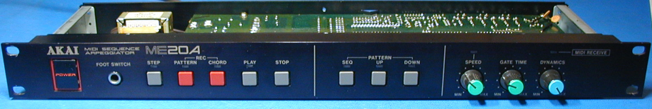
A firmware re-do for the AKAI ME20A Sequencer
Someone recently asked me if it was possible to add MIDI clocking to the AKAI ME20A stand-alone sequencer/arpeggiator. I took the bottom cover off of his unit and saw this:
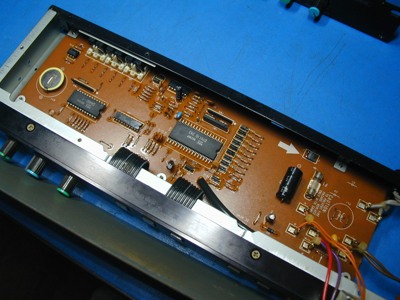
Not looking good. No external EPROM, so all of the code is inside the NEC upd7811G CPU. The only other chips are a battery-backed 2K byte SRAM, an address latch for the SRAM, and two other chips for the MIDI interface. Adding MIDI clocking would require a second MIDI input, and a second serial port in the CPU to go with it. Not a simple upgrade. But I decided to forge ahead and not let common sense stop me. Here is the result:
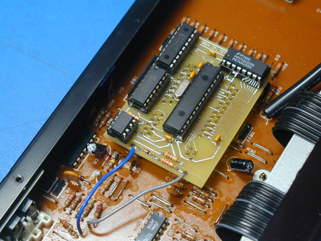
The first task was to draw out the schematic for the ME20A, to see how the 7811G pins were being used. Here is my schematic for a stock ME20A. Next I needed to design a circuit to replace the 7811G, and add support for a MIDI clock input. It was easy to re-purpose the MIDI thru jack to be a MIDI clock input instead. I wanted to stay with through-hole components, but was unable to find a suitable PIC chip with two serial interfaces. So I used a second PIC chip, just to get its serial interface, and clocked both chips from the same crystal. The spare pins on the second PIC chip were used for driving the front panel LEDs. Two other logic chips plus the MIDI opto-isolator completed the design. Here is the schematic for my CPU replacement pcb. Note that this circuit is very specific to the way that the 7811G is used in the ME20A, and could not be used to replace a 7811G CPU in any other application.
Of course new firmware was needed for both PIC chips. I decided not to try to replicate the original functions of the ME20A, but to redesign it instead. Here are the new features:
1) Four (step) sequences can be recorded and played. Up to three notes per step (chords) can be recorded. Each sequence can hold up to 250 notes. Velocity is saved for each note. A single MIDI channel is also saved for each sequence. Sequences are saved in battery-backed SRAM.
2) Playback rate can be adjusted with a front panel control, or can be set by MIDI clock.
3) Playback gate length can be adjusted with a front panel control in either clock mode.
4) During sequence recording, input notes can be fed to MIDI out if desired. (For use with a controller)
5) Sequences can be transposed during playback by playing notes. Offset is measured relative to middle C.
6) Real time arpeggiation is supported. Up to 14 notes can be arpeggiated. Notes can be latched and held. Modes are up, down, up/down, and random. 0,1,2, or 3 octave transposition of the notes (along with the original ones) can be selected with a front panel control.
7) Arpeggiator clock rate can be adjusted with a front panel control, or can be set by a MIDI clock.
8) Arpeggiator gate length can be adjusted with a front panel control in either clock mode.
Although the 7811G package has pins which are closer than 0.1" apart, if we look at each side of the chip, there are two rows of pins offset from each other, and these rows do have 0.1" spacing. So two rows of socket headers can be used on either side, and mating pins can be used on the pcb. This allows (carefully) plugging and unplugging the CPU replacement pcb if desired. Alternatively, wires such as trimmed resistor leads, or solid core wire could be used to permanently mount the daughter board to the ME20A board at a lower cost. This is a much riskier option. If there is a solder short on the underside of the daughterboard, you wouldn't be able to access it for a repair.
Installing this board requires very good soldering skills. First the old CPU must be removed. The safest approach to avoid PCB damage would be to cut all of the pins from the body of the chip with small (sharp) diagonal cutters, then de-solder each pin and remove it carefully. Of course at this point, the old CPU is destroyed, so there would be no going back.
Please note: Taking an ME20A apart and replacing the CPU must be done very carefully, or damage to the unit could result. It should only be attempted by someone familiar with this type of work. I will not be responsible for any damage to any unit caused by either proper or improper use of the code offered here.