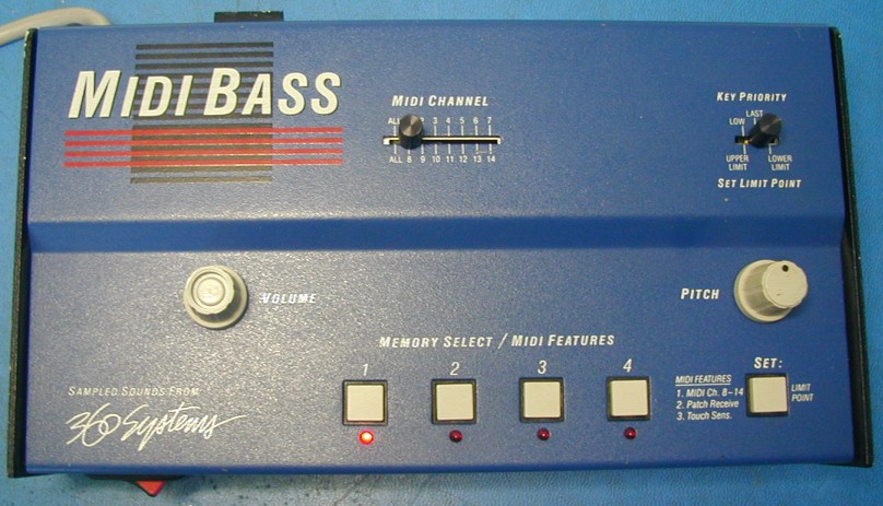
360 Systems MIDI Bass

Someone contacted me recently asking if it might be possible to make new sound EPROMs for the MIDI Bass. It turns out to be pretty complicated.
Some new schematics:
Having easy to read schematics is a great asset, both for learning how things work, and for doing any repairs. I couldn't find any schematics on line for this unit, so I decided to capture them myself. Here is an archive containing them. Use these at your own risk, and let me know if you find any errors.
Some circuit details:
Note: These are my own ideas about how the circuit and the code works. I was not involved with the design of the MIDI Bass, so there may be errors.
The MIDI Bass design has sockets for four 27256 EPROMs. Each of these is 32K bytes, and the 8031's address size is 64K, so they can't all be available for reading at the same time. Since only one sound can be played at a time, the designer decided to have just one EPROM enabled at a time. This means that each sound EPROM needs a copy of the 8031 operating code. Also, at boot, just one of the EPROMs must be selected. To accomplish this, three of the EPROM chip enables were designed to be active low, and the EPROM 1 enable was made active high. On the 8031, Port 3 is initialized to all 1's at reset. This enables only EPROM 1 so the CPU boots using the code in this chip.
2K bytes of each EPROM, starting at offset 4000H (16K) are allocated to the code. Since the CPU starts executing from address 0 after reset, address A14 is inverted before feeding the EPROMs, to address the 2K of code. Each EPROM has 30K bytes available for samples. Some sounds use two samples, and some use three. The samples were recorded at different pitches (multi-sampled) to give better fidelity over the playback pitch range.
The samples contain 8-bits, and are u-law coded. The DAC is a u-law one and converts the samples back to the original waveform. Many drum machines in the 1980's also used 8-bit samples with u-law coding, as it provides performance similar to 11 or 12-bit linear samples, but uses only 8 bits.
The code in each EPROM is customized to play back the samples in that chip. The filter cutoff can be controlled by the CPU, and is set differently for each note. There is a slight difference between the filter values used for different sounds as well. The cutoff is set at the beginning of the sound and does not change.
The DAC reference voltage, which sets the level (volume) for sample playback can also be controlled by the 8031. It can be set to a constant level, or can be MIDI velocity-sensitive. The level is set by the 8031 at the start of the sample.
The 8155 chip contains a 14-bit timer/counter. The front panel pitch control varies the frequency of a VCO chip, the output of which is used to clock this counter. The counter divides the VCO output by a value set by the 8031 based on the recorded pitch of the sample being played, and the desired pitch, which depends on the MIDI note being played. The divider can also be varied when MIDI pitch wheel messages are received. For each sample in the EPROM, there is a table of counter divider values to use for every MIDI note which uses that sample. If three samples are used to play a particular sound, there are three tables.