Multivox MX-312 Motor Replacement project
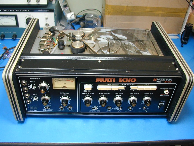
I was recently asked to help find a replacement motor for a Multivox MX-312 tape echo unit. I found a youtube video which explains how the motors are damaged. The capstan flywheel slides down the shaft and rubs on a screw below it. This creates a lot of extra friction, which causes the motor to overheat and burn out. (The 500mA motor circuit breaker apparently isn't enough protection) Here is a photo showing the scoring on the bottom of the flywheel from this rubbing:
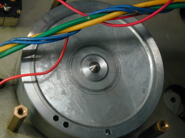
I used Loctite 620 to secure the flywheel after sliding it up on the shaft. But the damaged "FG servo" motor had been removed several owners ago, and replaced with a DC motor with no speed control. At first, I was hoping to find a suitable FG servo motor and re-use the existing motor control circuit, but the motors that I found were mostly from turntables, and after thinking about it, I realized they would all spin clockwise, and I needed a motor that would spin counterclockwise. Maybe I could have made one work, but I decided to use a DC motor with PWM speed control and no tachometer/FG output. Also, Jameco carries a number of small DC motors, which come with the specs needed to do a design.
The shaft of most small DC motors I found was 2mm in diameter, but the inside diameter of the belt pulley was 3 mm. Luckily I found that McMaster-Carr carries stainless steel tubing with 3mm OD and 2mm ID (#50415K17) This worked well as a shaft adapter (I secured it with Loctite 620):
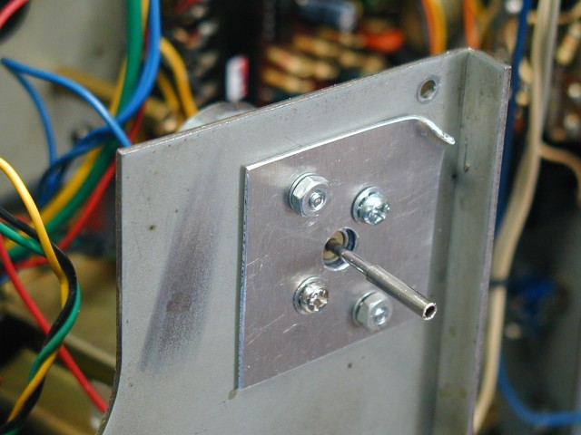
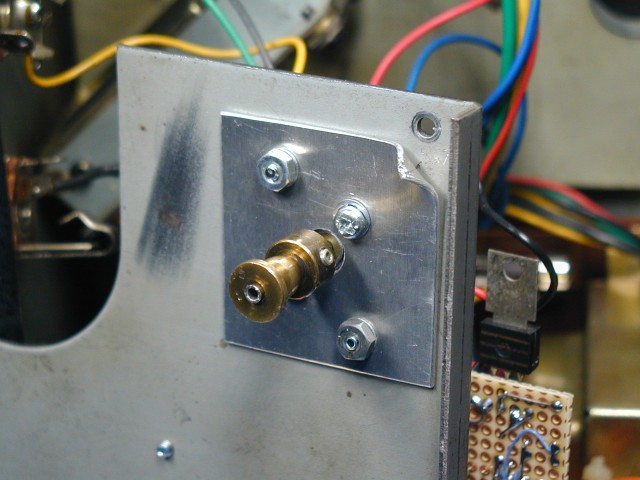
Note: The pulley sets screws press against the 2mm motor shaft, not against the shaft adapter.
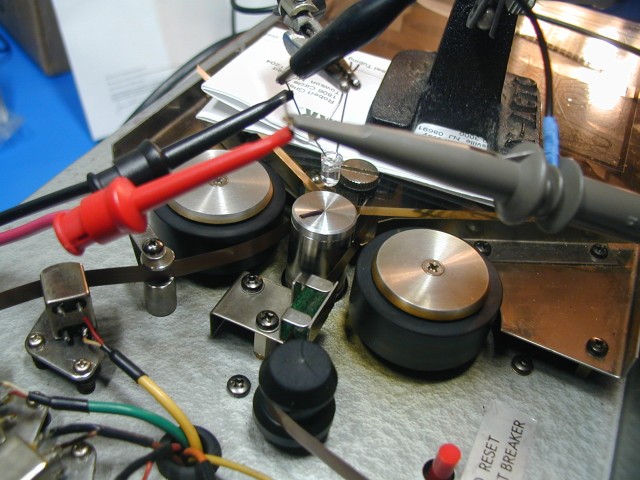
I found a web page describing a 555-based PWM motor control circuit. Here is my version of it. In the MX-312, the motor circuit is fed from a separate winding on the power transformer, with its own rectifier and filter cap. Red and blue wires connect this voltage to the motor control board. I decided to regulate this voltage, to keep the motor speed as constant as possible. With the Jameco motor that seemed to be the best candidate (#174693, RF-370CH-10670-19.5), I ended up using the R1 and R2 resistor values shown, plus the original speed/delay potentiometer, to achieve the desired speed range. To measure the capstan/tape speed, I used a white super-bright LED fed from a pulse generator as an improvised stroboscope and used my oscilloscope to measure the pulse frequency when a line drawn on the capstan appeared to be stationary:
Here is my breadboard implementation of the PWM motor control circuit:
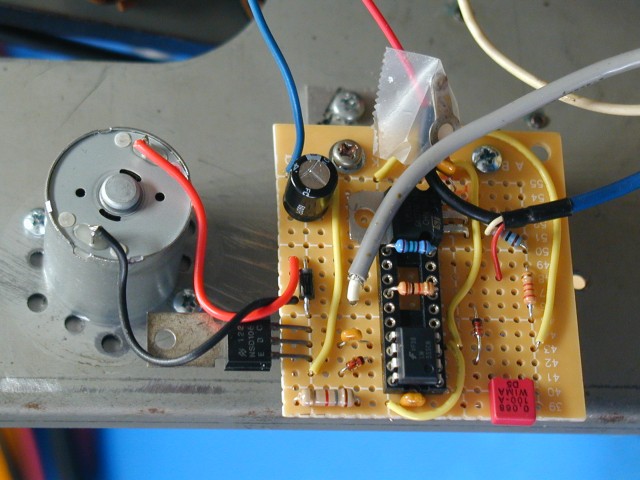
I used a socket for the resistors so that I could try different values, and then soldered the leads. The blue cable shield lug was connected to chassis ground after the above photo was taken. The gray shielded cable connects to the formerly unused end of the speed pot, as needed for the new circuit.
To confirm that I had the correct tape speed, I monitored the output of the MX-312 with an oscilloscope, and fed in short bursts of a 1 KHz tone. On the 'scope I could see the original burst, plus the delayed one, and measure the delay time for different speed settings.
Another thing I discovered about this unit was that someone had replaced the mounting "sponges" for the reverb springs, and had re-mounted the springs with the output end right next to the power transformer. The reverb signal contained quite a bit of induced 60 Hz hum. The output coil is much more susceptible to hum pickup than the input one, which is why the springs were originally mounted with the input coil end near the transformer. Rotating the springs 180 degrees reduced the hum to a very faint level.
A rubber drive belt that seems to work well in this unit is the FRX12.0 from vintage-electronics.net
Some Technical Details:
The capstan diameter at the pinch rollers is 17.9mm. The tape speed is specified as 12 to 24 cm/sec. This corresponds to capstan rates of 2.13 to 4.27 rev/sec. The flywheel diameter is 75mm. The motor belt pulley at its widest diameter is 7.0mm, so the motor spins 10.68 times for every capstan rotation. So the motor speed range is 1367 RPM to 2735 RPM for the listed tape speed range. The motor needs to turn counterclockwise. The motor I used draws 8.4 mA at 12.0 VDC, with no load. With the motor + belt + flywheel assy, but pinch rollers not engaged, the current increases to about 28 mA. With the pinch rollers engaged, and the tape being fed normally, the current increased to 34 mA.
My assumption was that the flywheel would smooth out tape speed fluctuations, and not the motor, and that if the motor could get the flywheel spinning at the correct speed with the friction of the tape applied, that was all that was needed. Unlike a normal tape deck which has varying supply reel and take-up reel tension applied to the capstan, an endless loop system should have relatively constant tape tension, so speed regulation should not be as important, or so I thought. But with the motor that I used, I can notice some speed variation at the slower motor speeds. One way to check for this is to feed in a constant frequency tone, and monitor the PA output signal, which has only the effects and not the original mixed in. Any speed fluctuation is easy to hear. The splice is thicker than the rest of the tape, and creates more drag as it feeds through the tape path. Also, the tape loop itself probably has one or two bends created by the way it was folded up for shipping. I am now thinking that a motor with a higher maximum torque capacity (which would draw more current) would do a better job of holding the tape speed constant despite small changes in the back tension. Hopefully as the (new) tape loop is used more, the speed fluctuations will diminish. It's certainly usable as is, but could be even better.
The MX-312 has an adjustment for back tension of the tape, as it feeds into the pinch roller before passing over the heads. If you look at various web pictures of the MX-201 and MX-312 you can see that Multivox had at least three different versions of this mechanism. On my unit, a small screw pushes a felt pad against a fixed round plastic tape guide. The applied pressure can be changed using this screw. Too little pressure will allow the tape to flop and not sit against the heads. Too much pressure will cause increased tape and head wear, and also make the motor work harder. On the unit I worked on, the round plastic tape guide had a flat worn into it where the tape had been rubbing. Since this guide is fixed, I rotated it 180 degrees to move the flat away from the tape path. I did the same thing to the other round plastic tape guide.
Please note: I don't have a lot of experience with small DC motors. I hope the information provided here will be of assistance, but your mileage may vary, and I can't guarantee any specific result. I will not be responsible for any harm to your unit or to you caused by either proper or improper use of the information offered here.