MXR 129 Pitch Transposer
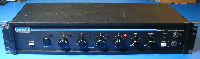
I recently purchased this late 70's unit (shown above), in non-working condition. No schematics were available on the web, and all of the chips on the top pcb had their markings removed to prevent copying (and repair). Luckily, someone local to me had the schematics and generously offered to copy them for me. So now I am making them available here, in case anyone is trying to repair a unit. The connectors were not numbered, so I have numbered them. I had to assign the numbers myself, as I couldn't find any indication on the connectors or the pcb as to which was pin 1. I have indicated on the component placement diagrams which ones I am calling pin 1. Also, I have put together a document describing the operation of the circuit, at least as I understand it. Since I had nothing to do with the design, there may be some mistakes, but it may be helpful anyway. On my unit, TL072 U26 on the top board was toast, preventing the input signal from being digitized and stored. Also, some chips associated with the touch preset selection were missing, but they are standard 4000-series and were easy to obtain.
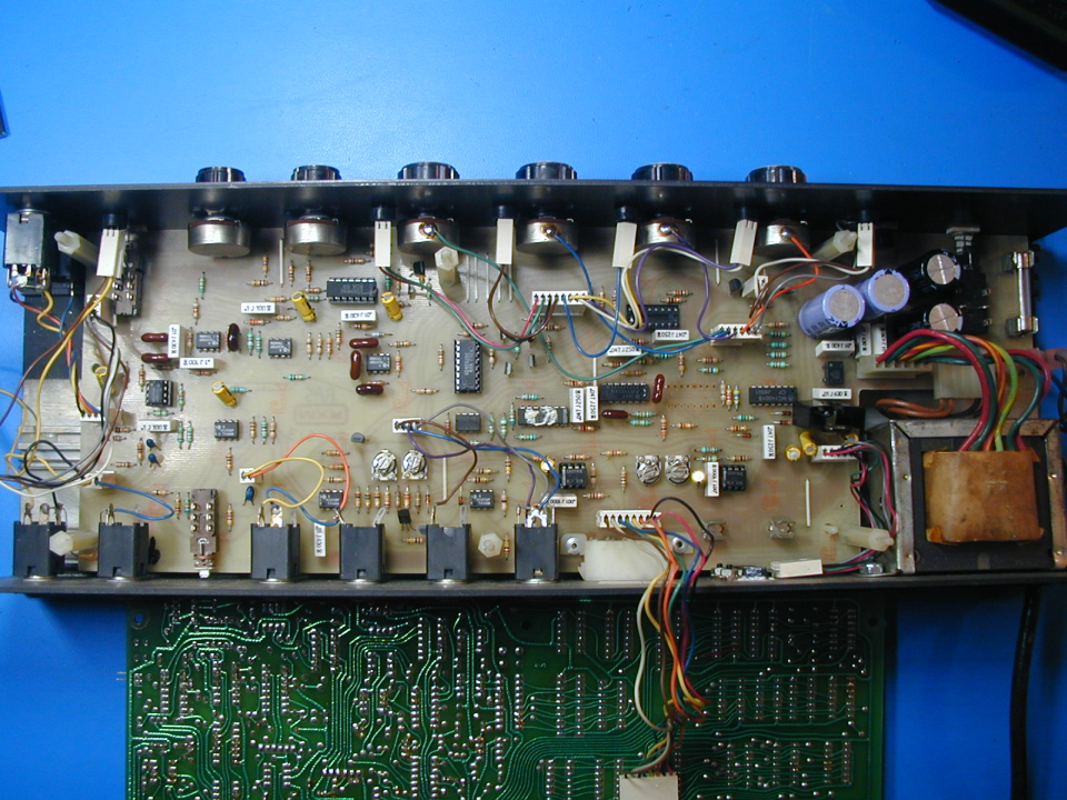
Here is a photo of the bottom board in my unit. The missing chip is called "14171" on the schematic. I didn't find that number anywhere, but it can be replaced with a CD40174.
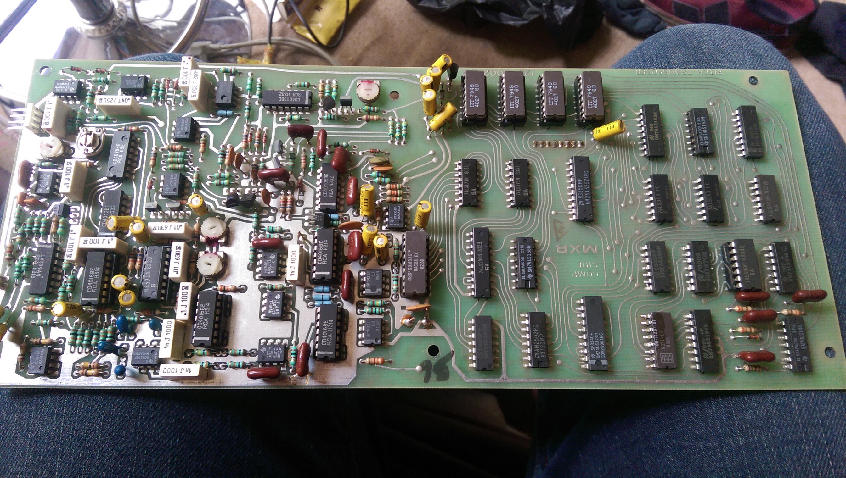
And here is a link to a great photo (used with permission) of the top pcb which still has the markings on the chips.
Here is a block diagram of the MXR129, which was part of a review of the unit in a French-language publication back in the day.
Here are the schematics for the bottom pc board.
Here are the schematics for the top pc board.
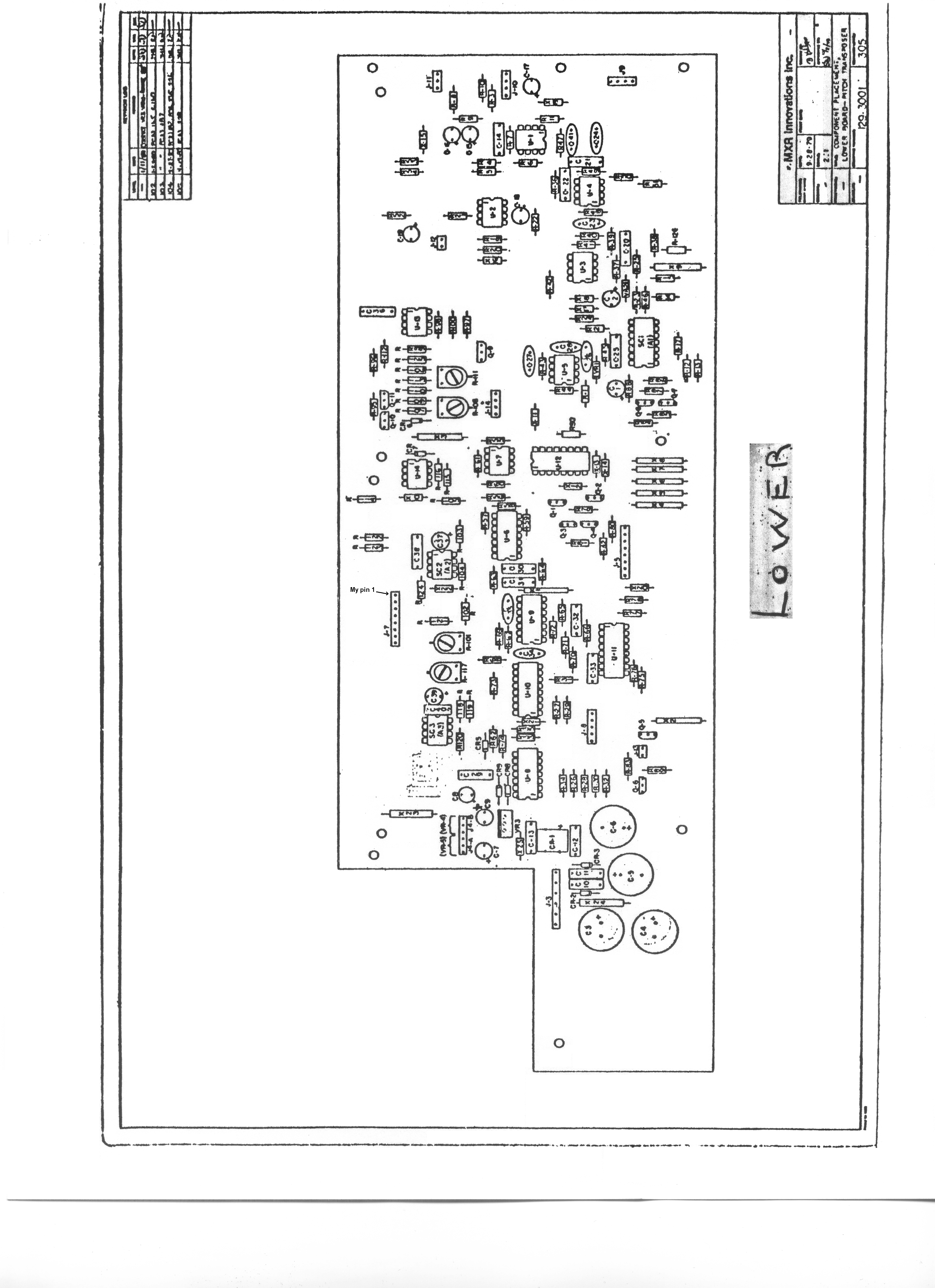
Here is a component placement diagram for the bottom pc board. I cleaned it up a bit as it was a copy of a copy of a copy...
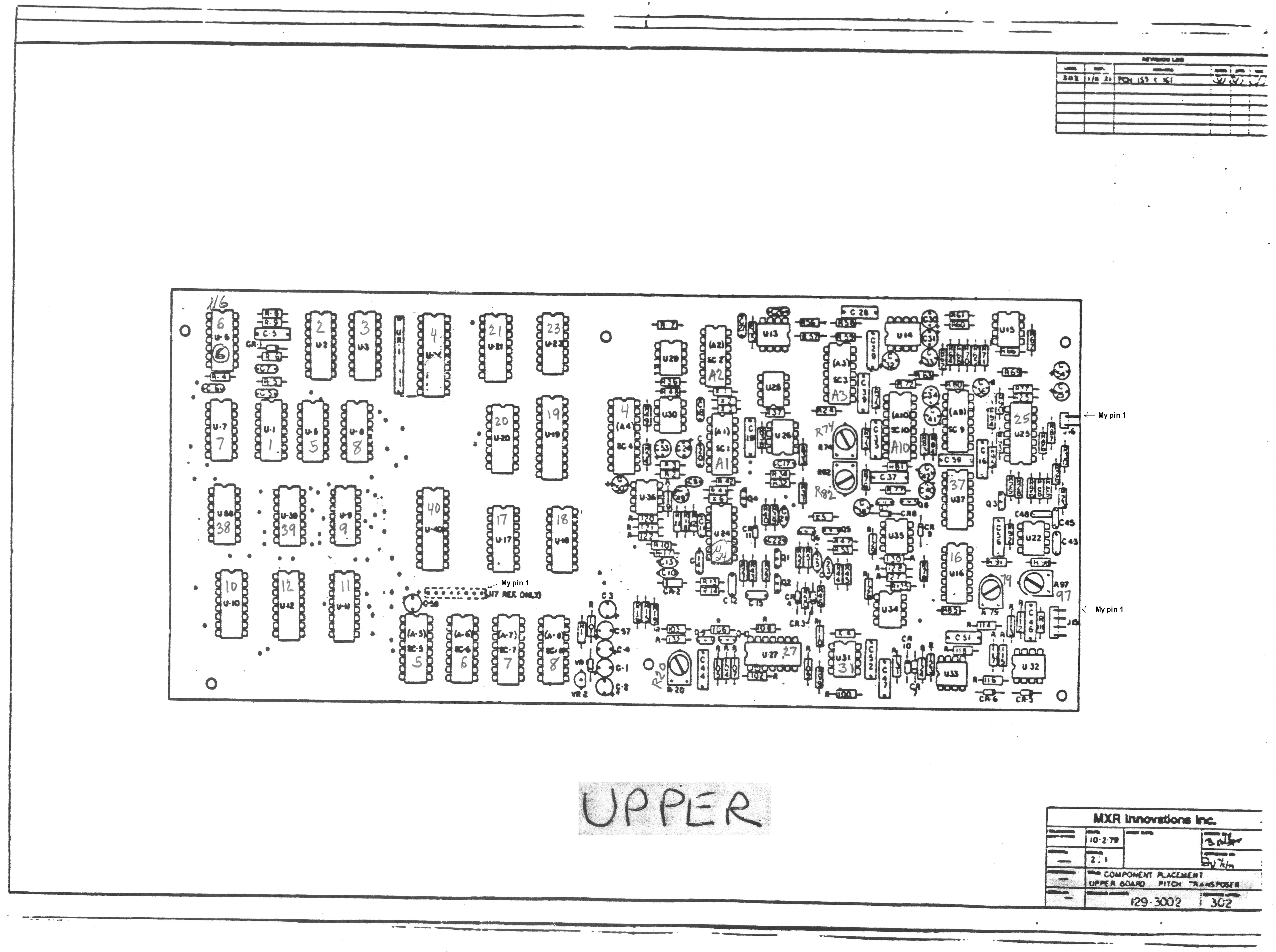
Here is a component placement diagram for the top pc board. I cleaned it up a bit as it was a copy of a copy of a copy...
Here are the calibration instructions for the bottom pc board.
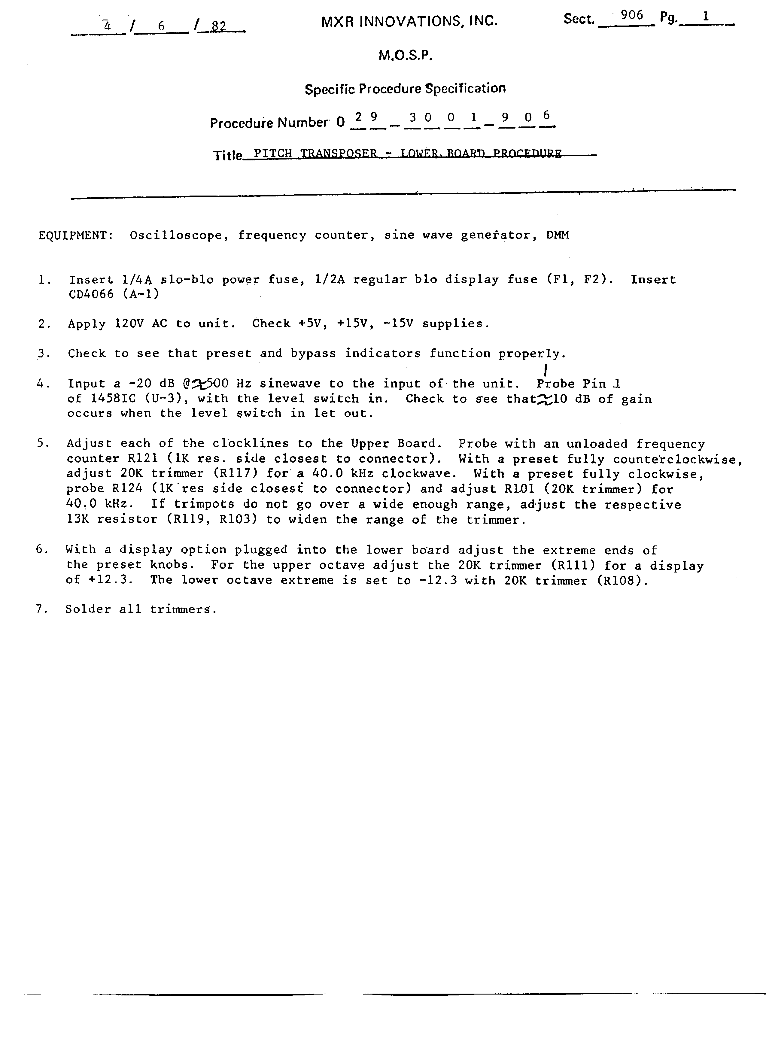
Here are the calibration instructions for the top pc board.
Here is a timing diagram showing the signals that are generated by the PROM chip. This was with the schematics when I got them. Possibly drawn by the designer?
Here is a dump of the PROM data, showing the resulting write and read sequences.
Here are the schematics for the optional display
And finally, here is my circuit description document.
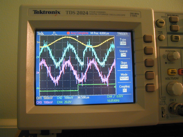
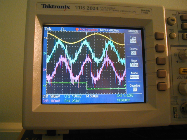
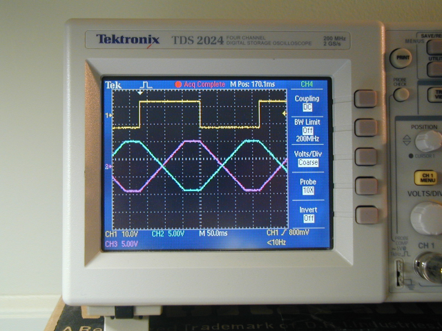
Below are some oscilloscope pix that show the discontinuity that happens in the output streams when we overrun/underrun the circular buffer. The yellow trace is a 300 Hz -10dBu line input sine wave. The blue trace is one of the output streams, at U13-1. The pink trace is the other stream, at U13-7. The green trace is U27-1 ("splicing clock"). (I took these photos with a rather low input level, which is why the waveforms look so noisy.) For one polarity of U27-1 change we have a discontinuity in one of the streams:
For the other polarity of change, it's the other stream that can glitch:
Here is a photo that shows the crossfading that is constantly going on between the two streams, in sync with U27-1 (yellow trace). The other signals are the gain controls for the two halves of the NE571, U34-1 and U34-7.
Link to the original designer's web site:
The MXR 129 and 113 were designed by Tony Gambacurta. He talks about creating them here.
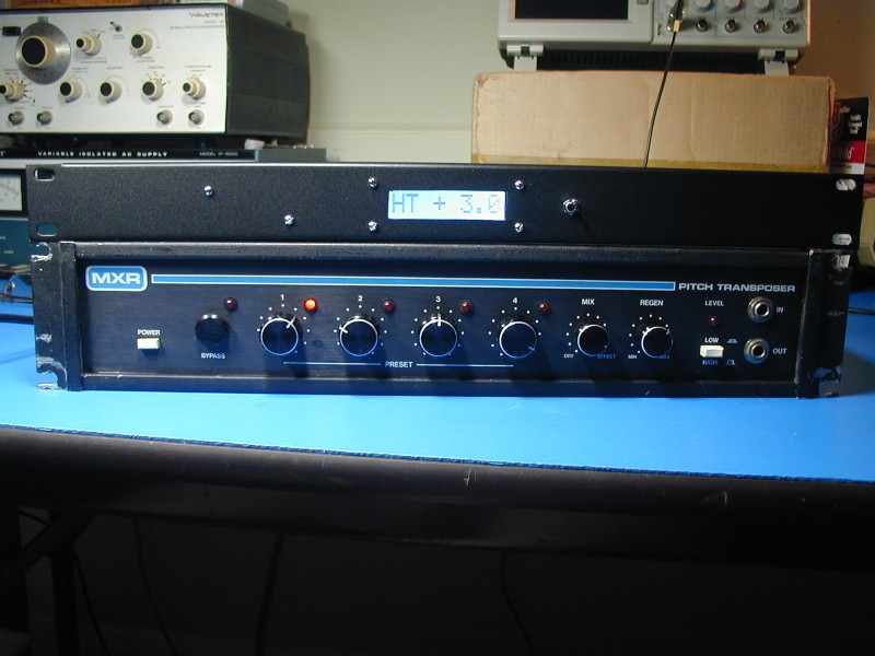
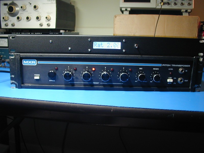
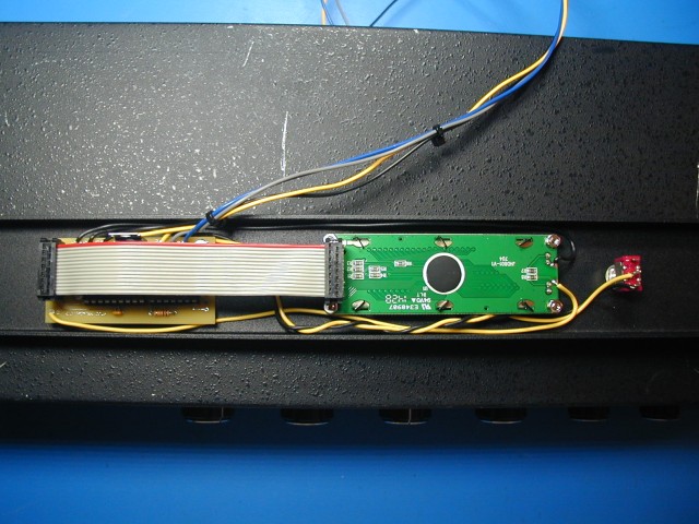
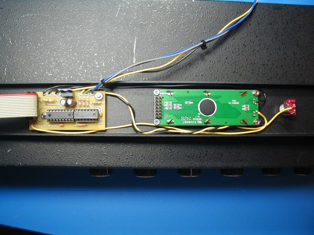
MXR 129 Display DIY PCB and PIC are Available
I have implemented an MXR 129 display, using an 8x1 backlit LCD module and a PIC microcontroller. It implements both display modes (offset in units of half-tones and output to input frequency ratio) I assembled mine on the back of a blank 1U aluminum spacer. The spacer and the LCD module were very reasonable on ebay. I was not able to find the Molex connector that mates with the MXR129, but individual connector contacts can also be for this. Only four wires are needed. If anyone is interested in making one of these, I can supply a blank pcb and a programmed PIC chip. I have one extra 8x1 LCD as well. The rest of the components are readily available and there aren't that many of them. Good soldering skills are needed to build something like this. I will not be offering assembled boards or displays. I chose an 8x1 LCD with nice big characters. (Surenoo Technology Model STD0801A) If a different one is used, the pinout of the connector might be different, requiring individual wires to be used instead of the ribbon cable. Also, some backlights draw more current than others. I set the backlight current at just 15 mA, as that produces a nice bright display while minimizing the extra load on the MXR129 power supply. My code will also work with a 16x1 LCD, but will only use the first 8 character positions. Here are some photos showing the display. The backlit LCD looks much better in person than in my photos.