MemoryMoog Auxiliary Display
A local friend was repairing a MemoryMoog recently, and was frustrated by the fact that calibrating the oscillators requires you to watch the tiny LED display, which is facing away from you and upside-down when the front panel is raised. I decided to see if somehow the display data could be intercepted and used to drive a second (temporary) LCD display during calibration. It turns out that all of the needed data is in just two ribbon cables feeding from the CPU board to the left front panel. But +5V and ground are also needed, so the final connection scheme ended up being slightly different. To connect the aux display, one IC is removed from the CPU board (temporarily), and a DIP header is plugged into its socket. A ribbon cable is also unplugged from the CPU board and a DIP header plugged into its socket. Then the unplugged ribbon cable is plugged into a socket on the aux display interface board. The display data is captured and fed to a PIC chip, which figures out which characters are being displayed, and drives a 16x2 LCD module. In calibration mode, decimal equivalents of the hex values are displayed on the second row. To get the firmware working, I hand wired a prototype. Initial testing was done with just the PIC chip, by adding test code to simulate data coming from the MemoryMoog. Here is how the prototype looked:
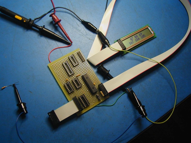
The prototype was completed, and has been used during Memorymoog oscillator calibration. It worked as expected.
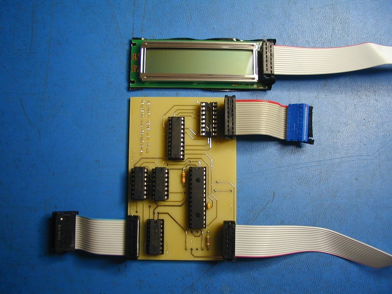
Here is the pcb version:
Pretty much any message that appears on the LED display will also appear on the LCD one. It appears that during autotune, after writing "Tuning" to the display, the code accesses the display address again, which clocks an incorrect character into the third position. At this time, the MemoryMoog display is blanked, so we don't normally see this. I havn't looked into this yet. So far we have not seen any issue with other messages.
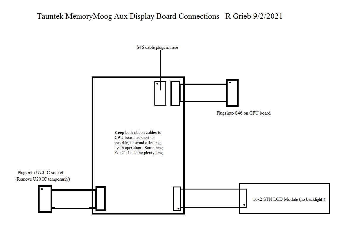
I will offer a pcb and PIC together for $40 plus shipping, for anyone who wants to assemble a display for their own use. I will not be offering fully assembled boards. Here is the schematic. Here is a parts list, and here is a diagram showing how the display connects to the synth.
I will not be responsible for damage to any instrument caused by either proper or improper use of the
information presented here.