Oberheim OB-1 Analog Monosynth misc and new programmer information.
I was working on an Oberheim OB-1 recently, and thought to share some of what I have figured out, as I did not find a full service manual on line. The schematics are available, thankfully. I ended up replacing a number of 741 op amps and one 1458 type, all on the synthesizer pc board. Even though these were used as amplifiers, there was a DC voltage difference between the inverting and non-inverting inputs, and the outputs weren't working properly, so I replaced them with sockets and new parts. Also, several of the white-ish 100K trimmer pots had gone funky and were intermittently disconnecting the wiper, which caused random crackling noises in the output signal. It took me a while to figure out that the pots were the cause. The three trimmers that were flaky were the two feeding into the inverting inputs of U11, and the one feeding into U31 (T16). The first two seem to trim the waveform shaping. I adjusted them by setting the front panel waveform pot fully clockwise, selecting pulse waveform, and setting the trimmer for exactly 50% duty cycle at the output of U11. Probably all of the white 100K trimmers need to be replaced.
The synthesizer pcb does not have any IC designators marked on it that I could find. I created a drawing that shows the placement of the chips on this board. Here it is. Several chips had no ref des shown on the schematic, so I numbered them myself. I used a reverse image instead of the original photo, so that it would be much lighter than the dark green original. This will save toner or ink if the image is printed. (I don't have an ultra-rare pink synthesizer pcb!)
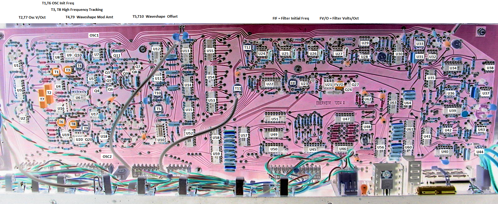
On the schematic I downloaded for the original envelope generator design, the two sets of control voltages are swapped, so that the "2" cv's connect to envelope generator 1 and vice versa. This is a mistake. If you change the "1" cv names to 2 and the "2" cv's to 1, your schematic should be correct. The connections shown to the S&H op amps for these eight voltages are correct.
The synthesizer pcb schematic that I downloaded shows a 180K resistor in parallel with the 100K feedback resistor on U8 and U19. On my unit, the 100K resistors were present, but the 180K resistors had been replaced with zener diodes, presumably to limit the maximum positive voltage at the output of the op amps. The two installed zeners were not the same voltage value, so osc 1 U-6 had a voltage range of 0-3.3V DC. Osc 2 U19-6 had a range of 0-4.2V DC. The zener installed for osc 1 looks to be original, whereas the one for osc 2 looks like it might have been replaced at some point. Not sure what the correct voltage rating is for this part. The anode end of the zener is connected to the inverting input of the op amp.
One of the more interesting (to me, anyway) parts of the OB-1 design is the programmer. Later synthesizers implemented this function with some sort of microprocessor, which greatly simplifies the circuit relative to the OB-1 version. Doing it with discrete 4000-series chips must have been an interesting design challenge. And to further complicate the design, only a single 1024x1 SRAM was used, so potentiometer 6-bit parallel values had to be written and read bit-serially. I wrote up a short description with some information about how the programmer circuit works, or at least how I think it works. Here it is. Hopefully this will be helpful to anyone interested in this circuit, or trying to repair one.
On my unit, flip flop U32 in the programmer was not switching so it was stuck in MANUAL mode. Replacing the chip fixed that.
A new MCU-based programmer pcb is now available for the OB-1
Note: After assembling and shipping roughly 50 OB-1 programmer pcb's, I have decided to stop offering assembled boards, as of December 2022. If you want to buy parts for the board and assemble it yourself, or you have someone who will do it for you, I can supply the bare pcb and a programmed PIC chip for $45 plus shipping.
I have designed a replacement for the Oberheim programmer with the following features:
1) 64 programs in 8 banks of 8
2) Programs are stored in non-volatile EEPROM. No battery needed.
3) After a program is loaded, only controls that have moved are "live", so patch editing is now possible.
4) Manual mode forces all controls to be "live".
5) Optional (non-volatile setting) periodic flash of current bank selection
6) Optional (non-volatile setting) quantization of coarse freq for oscillator 1 to octaves
7) Comes with 24 pre-programmed patches, which can be over-written later if you chose
8) Smaller pcb mounts on four of the existing standoffs, providing better access to pcb underneath
9) Implemented connectors are the same as original programmer for easy installation
10) All IC's are socketed. All components are through-hole.
11) 20-turn trimpot for easier one-time oscillator tuning adjustment
Note: Connections to external cassette interface and external program selector are not implemented
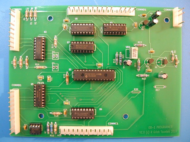
Here is a photo showing the new programmer pcb:
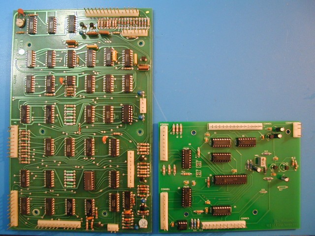
Here is a photo comparing the original programmer to the new one:
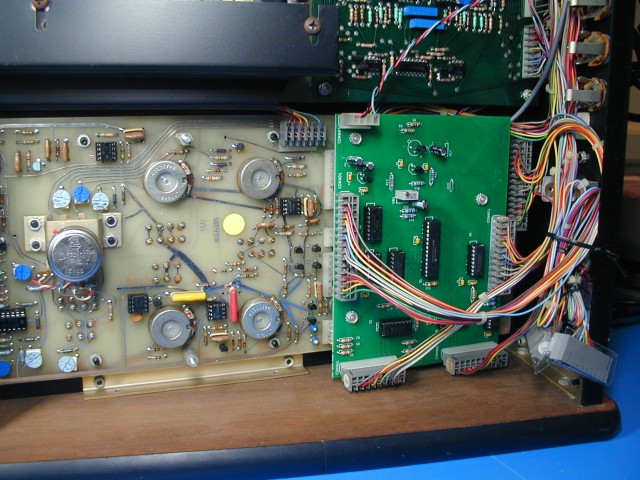
Here is a photo showing the new programmer installed in an OB-1. The battery has been removed, and the cables associated with the rear panel external cassette interface and program selector are not used.
 .
.
Here is a schematic of the new programmer. Here are instructions for installing it. And here are some instructions for using it.