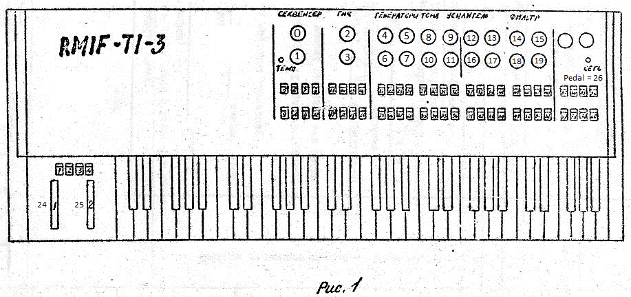
An 8-voice late 1980's Poly-synth from Riga, Latvia - The RMIF TI-3
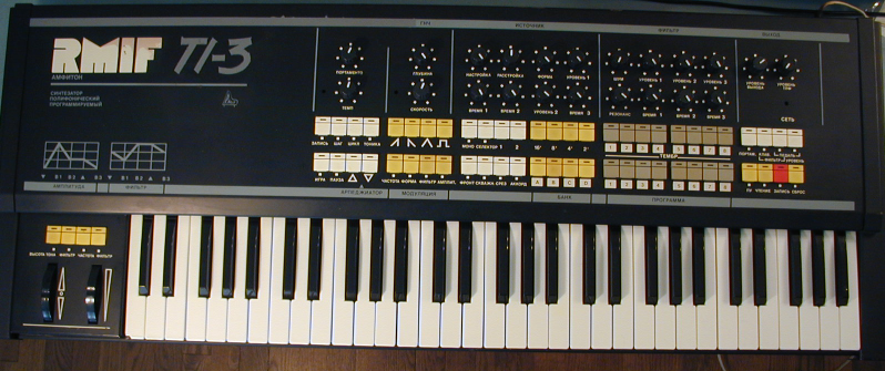
I recently volunteered to work on an RMIF Opus string synthesizer, just to learn a little about analog synths made "behind the iron curtain". That experience got me interested in other synths made by the same company, specifically, the TI-3. Unlike the Opus, the TI-3 is a microprocessor(8080)-based analog poly-synth with 16 DCO's, 8 24 dB/oct Moog-style low-pass ladder filters, an arpeggiator, and a real-time sequencer. 192 factory EPROM patches are provided as well as space for 64 RAM patches. At first I started trying to understand a code EPROM image which I found on-line, then I decided to get an actual unit and learn about the hardware design as well. Along the way I decided to capture schematics of the five different pc bds, as they were nowhere to be found on the web. This is my way of "giving back" to the web as it's been incredibly helpful to me.
I found a synth for sale near St Petersburg, and arranged for it to be shipped to the USA. Bought a 110 to 220V voltage converter for it as well.
Several Unusual Features of the TI-3:
The DCO waveforms have adjustable rise and fall times. Using these, one can achieve sawtooth, backwards sawtooth, triangle, and pulse waveforms, plus some in-between ones. DCO2 has adjustable pulse width, which can also be modulated by the LFO. DCO1 pw can be set to either 50% or narrow.
It seems a lot of effort was spent on the Mono (Unison) mode implementation. Each voice has its own storage for patch parameters. It's possible to edit each voice separately in this mode, and also to enable or disable each voice separately. So any combination of the eight (possibly different) timbres can be played in unison. When a "mono" patch is saved to RAM, all eight voice programs are saved in eight locations. When a mono program is read from RAM or EPROM, eight programs are read. (In Poly mode, just one program is read, and written to all eight voices)
Portamento is supported in Poly mode, but the oscillators don't glide from one note to the next, as in Mono mode. Instead, an interval can be set by pressing two keys on the keyboard. This interval is then used to determine the starting point for poly glide. If the two notes are an octave apart, then each voice's glide will start one octave from the note played and glide to it. The direction of the glide is determined by which of the two notes used to set the interval was higher, the first or the second. The portamento speed is adjustable. So you can set up an octave descending glide, or an octave ascending one, and glide up to eight different notes at a time.
A Few Technical Details:
Anyone who is familiar with the design of analog poly-synths from the 1980's will know that most were made using either the Z80, 6809, or possibly two processors, as in the PolySix, Multitrak, and some others. I had not heard of any synth using a single 8080 CPU, much less one with 8 voices. I think the 8080 may have been the only CPU available to the designers at RMIF, even though the TI-3 was designed in the late 1980's. A number of things were done to improve the performance while using the 8080, both in hardware and in software. Here are a few of them:
8080 and Z80 CPU's have two separate address spaces. One is for memory, and the other for "peripherals" such as UARTs, or other hw to interface to switches, LED's etc. Code talks to those two areas separately, and there are special instructions for writing to I/O addresses versus memory addresses. A signal from the CPU indicates which kind of access is happening. In the TI-3, that signal is ignored, and many of the hw devices, such as the DAC, the LED's etc, can be accessed using either memory or I/O instructions. This unusual trick makes the code run a little faster in certain places.
Most synths from this era with many LED's to drive set up a matrix of rows and columns of LEDs. The CPU drives one row of 8 LED's, for maybe 6 mSec, then the next row for 6 mSec, etc in a loop. If there are ~60 LED's as in the TI-3, then there would be 8 rows of 8 LED's each. Each row would be refreshed every 48 mSec. Even though the LEDs would actually be flashing on and off, the flashing is fast enough that we wouldn't perceive it. This technique requires the CPU to stop what it's doing every 6 mSec and switch to the next row of LED's which takes time away from its busy workload. In the TI-3, the designers must have decided that the 8080 simply could not handle the processing needed to keep updating the LEDs, so a different approach was used. When the CPU writes out new LED values, a small register file chip stores the values for all eight rows of LEDs, and then cycles through them on its own when the CPU is busy doing other things. This removes the burden of constantly updating the LEDs from the CPU, at the expense of additional hardware.
A common technique used by synths from this era with many potentiometers to scan is to have a single D to A converter, used both for generating the sound hw control voltages, and also used with a successive-approximation sw routine and a comparator to A->D convert each potentiometer in turn, maybe 20 times each second. The TI-3 took a different approach. The CPU selects a particular pot to be converted, and writes it's index to a register on the front panel board. A separate DAC, successive-approximation controller chip and comparator are then kicked off to convert the pot voltage with no help from the CPU. After some time, the CPU reads the value and selects the next pot to be converted. This approach requires more hardware than the "standard" method, but reduces the load on the CPU.
The 8080 CPU does not have any sort of auto-incrementing pointer register, such as the ones in the Z80 or the 6809. But it does have a stack pointer which increments after each "pop" (memory read) instruction. The TI-3 code makes unusual (in my experience) use of this feature. Instead of only using the stack pointer to write to and read data from the stack, in many places the stack pointer value is saved, then it's pointed to a group of variables that the code needs to access, then a number of pop instructions are performed to read those variables into the CPU as needed. Pushes are also used to write the updated values back to RAM. After the routine has finished its calculations, the saved stack pointer value is restored and the routine terminates normally. This technique makes the variable accesses much faster, but the code is a little harder to follow.
Anyway, I have my TI-3 working now and have more or less finished capturing the schematics of the pc boards. Here is a zip archive of them. I will be working with these schematics for the next month (Dec/2015) or so, and may add some additional comments, notes, etc, so check back if you want the final ones in a few months. Also, I put together a list of cables and the pcb connectors that they mate with. Here it is. Some of the cables are interchangeable, so I can't be sure they are in the original position, but at least you can see what hooks to what.
Troubleshooting Information
Power supply trimmers are:
RP19 +12V, RP32 +15V, RP15 +5V, RP10 -5V, RP36 -15V One thing to watch out for: both the +5V and +12V supplies require a load in order to regulate properly. With no load, the +5V supply on my unit was +7.2V and the +12 supply was +16.9V When I loaded the +12V supply, it went right to 12 volts. When I loaded only the 5V supply, it stayed at 7.2 volts. For some reason, the reference for the 5V supply is derived from the +12V output. So if the 12V supply is not loaded, the 5V supply will be too high. This may have been to protect the CPU, which uses both +12 and +5. If the +12 is not working, then the +5 would also be shut down.
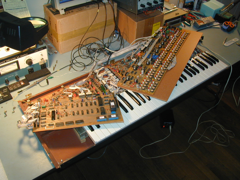
One thing that can make the TI-3 difficult to work on is the pc board physical arrangement, with boards stacked on top of each other. Murphy's Law says that the problems will be on the bottom board, of course. Here is a photo showing the boards positioned so that the synth can be powered up, but components on the bottom DCO board and the front panel boards can still be probed. The top DCO board was removed, as it was working OK, and was blocking access to the lower DCO board. The front panel boards were removed from the panel itself so that they could be accessed.
Determining which DCO's are working is relatively easy, as the eight voice outputs are accessible on the connectors from the DCO boards to the filter/VCA boards. I used an audio amplifier with a 1 uF non-polarized capacitor in series to block any DC voltage, and probed each of the connectors in turn. For this test you simply load a patch, turn on "Mono" and "Select" and then use the "1" and "2" switches to enable each DCO separately. It's easy to hear if a DCO is working and if it sounds the same as the other voices. When testing DCO1, make sure you try it in both "50% PW" and '"narrow PW" modes, as the circuits used are a little different. On my unit, I needed to replace an 8253, two CD4011's, a leaky 1 nF capacitor, and a number of op amps to get all 16 of the DCO's working.
Troubleshooting the filter/vca boards is also made more difficult by their being stacked on top of each other. I found it easier to remove these boards and work on them apart from the synth. I supplied +/-15V to them, and then fed in a triangle wave (capacitor-coupled) from my signal generator, 2V pk-pk I think. Use a separate power supply, or just a simple potentiometer, to feed in a 0-10VDC variable voltage for the VCA, Filter cutoff, and resonance control voltages. You need to connect the ground pin on the signal input connector to ground on the pc board to get proper operation. On these boards, I changed a number of op amps and several transistor arrays to get all of the channels working. I also found some resistors that were out of tolerance and replaced them. The NPN transistor arrays used are not available in the USA, so my plan was to make a small adapter pcb to allow using CA3046 types (different pinout) instead. As I was laying out the adapter board, I noticed that the two chip's pinouts are mirror images of each other. Pin 1 = pin 14, 2 = 13, 3 = 12, etc. This made it possible to install the CA3046's (electrically upside-down) in my unit with no special adapter board. After bending out the pins on both sides, I soldered one side's leads into the pcb, bent those leads to lean the chip over a bit, then connected the pins on the other side with wires. Here is a photo showing how it looks:
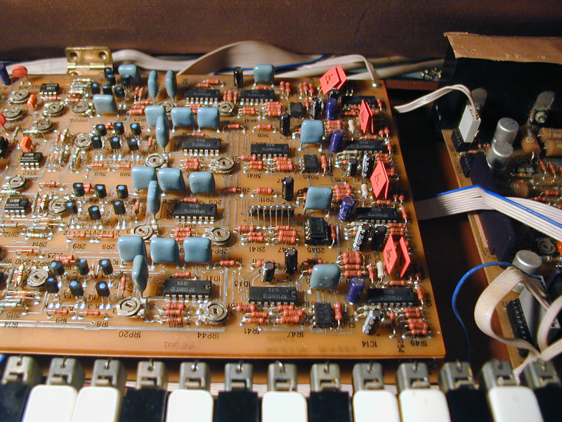
I have never mounted a chip this way before, but it works fine, and is not as tall as the blue capacitors. I replaced three of the transistor arrays on my boards this way.
Test Programs
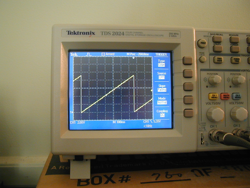
I have written some small test programs which may be useful for repairing a TI-3. The first one is a Sample and Hold test. Here is an archive containing the source code and a generated binary image. You must place this image at the correct location in whatever EPROM you are using. For instance, in a 27C256, you would place it at offset 6000h in the EPROM. If you use a different size EPROM, the offset will be different. This program does not use any SRAM. It generates a DAC ramp and feeds it to the selected S&H channel. Switches 1-8 on the top row select which voice is tested, and switches 1-8 on the bottom row select the sample and hold channel. Sample and hold channels are 0-7, and correspond to the channels of the demux chip. For instance, this photo was taken with channel 6 (switch 7) and voice 3 selected. Channel 6 is the VCA control voltage. It takes about 750 mSec to count through all 12 bits of the DAC. This program also tests the DAC, of course.
Here is an archive containing a small memory test program for the TI-3. It tests DS12 and DS13 with a walking 1's pattern. The test will halt on the first failure, displaying the failure address on the program select (top row 1-8) and program group (bottom row 1-8) LEDs. Address bytes are displayed with the LSB on the left, as that is how the TI-3 LEDs are arranged. After DS12 and DS13 are tested, DS14 is tested non-destructively by reading the data out, inverting it, writing it back, testing it, then inverting it again and writing it back and testing it again. Any failure will halt the test and display the failure address. Next DS7 and DS8 are tested by adding all of their bytes to form a checksum, and comparing that sum to the correct value for the factory EPROM data. If DS7 fails, 2222h is written to the LEDs. If DS8 fails, CCCCh is written. If all tests pass, you should simply see program select LEDs lighting 1,2,3 etc in a loop. The test will run until power is removed.
The RMIF TI-3 DS6 EPROM contains some interesting code that may be helpful. It appears to have been intentionally disabled, but can easily be re-enabled using the code here. The code reads from a special hardware address, and if the D0 bit is "0", it displays the measured 8-bit digital value for any potentiometer as it is being adjusted. The value and the "potentiometer select code" are displayed using the 1-8 LEDs on the top row for the pot value, and 1-5 on the bottom row for the pot select code. The select code is a value from 0-19 for the main pots and 24-26 for the two wheels and the pedal input. For instance, the shape adjust control is #8. You must enable the control panel to see this display, and also place a shorting jumper from XS16-3 to ground, which is on XS16-5. You can see from the CPU schematic that this jumper causes D0 to be read as "0" when address 7xxx is read by the CPU. The "normal" TI-3 code reads from 6xxx to check for the pot display. I suspect it was changed from 7xxx to 6xxx to disable the feature. I have changed it in the special version to read from 7xxx, enabling the pot display feature. Here is a drawing that shows the "pot select" codes. These codes are used in the hardware to select the correct multiplexer channel to read a particular pot.
A Minor Annoyance
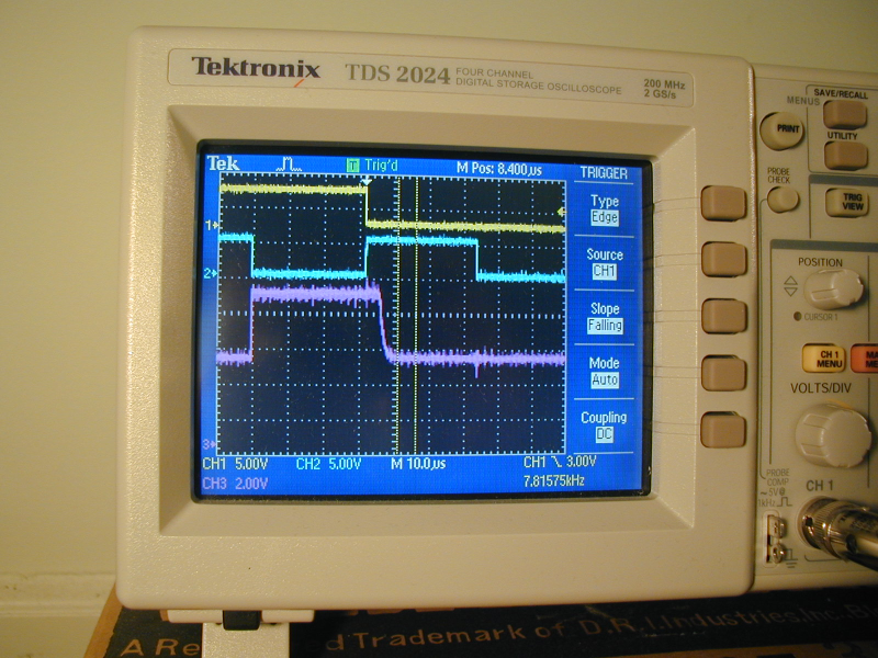
When I first powered up my TI-3, I noticed immediately that the "off" LEDs were not all completely off. They seemed to be affected by the states of other LEDs. I determined that this is caused by the four PNP transistors on the left front panel board VT9-12 not turning off fast enough. As a result, data from one row of LEDs affects the previous set, causing them to glow dimly. Here is a photo that shows the PNP collector switching well into the next LED "time slot": Yellow and blue traces are the 7.8 and 15.6 KHz clocks used to select the LED row. The violet trace is the PNP collector.
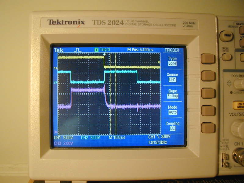
I decided to have a go at eliminating this issue by installing faster PNP transistors. But while I was waiting for my new transistors to arrive, I discovered a different solution. Thanks to the internet, I found something called a "Baker clamp". This is a way to add one or several diodes to a switching transistor circuit to prevent the transistor from saturating. This allows it to switch off much faster. The simplest implementation of this technique is to add a schottky diode from the transistor base to its collector. In this case, since the transistors are PNP, the anode of the diode connects to the collector and the cathode to the base. The diode will only be forward-biased when the collector voltage goes above the base voltage by roughly 0.3V I have added BAT48 diodes on VT9-12 and the "off" LEDs are much dimmer. It's not really a problem for me at this point. Here is a photo that shows VT10 switching off with the schottky diode installed.
About replacing TI-3 electrolytic capacitors
Be careful when replacing electrolytic capacitors in the TI-3. In some places the "+" polarity on the pc bd is wrong. Some places the polarity is marked one way on the top of the board, and the other way on the bottom. Some places no polarity is marked. Check the polarity of the old capacitor before removing it.
New Firmware for the TI-3:
I have been working on understanding the TI-3 operating firmware, to see if maybe I could improve it a little. I have fixed a few small code bugs, and changed the voice assignment order to a simple rotation. The original code was always using voice 1 if only one key was pressed at a time. This meant that notes with long sustain were cut off by the next note. (Thanks to Edwards for pointing this out to me) Also, the pot scanning is rather slow on the TI-3, with most pots scanned only once every 480 mSec. To address this, the designers alternated between three "fast" pots (the two wheels and the pedal input) and the other 20 (slow) pots. The three "fast" pots are scanned once every 68 mSec, or 15 times/second. In my new code, I only scan the wheels and the pedal if they are enabled to control something. If they are disabled, their "time slots" are used for the "slow" pots instead, so if both wheels and the pedal are disabled, the slow pots are scanned at about twice the rate in the RMIF code. I have moved the Filter Sustain pot to the "fast" group, so it is scanned much faster than before. Here is an archive of my current best TI-3 code. It may change in the future if I have more ideas. You need to place it at the correct offset for the EPROM size that you are using, of course. Only the DS6 EPROM is affected.
Turning a TI-3 into a TI-5:
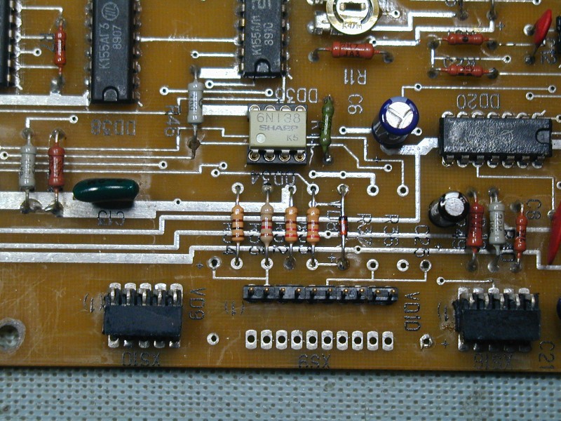
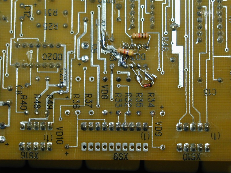
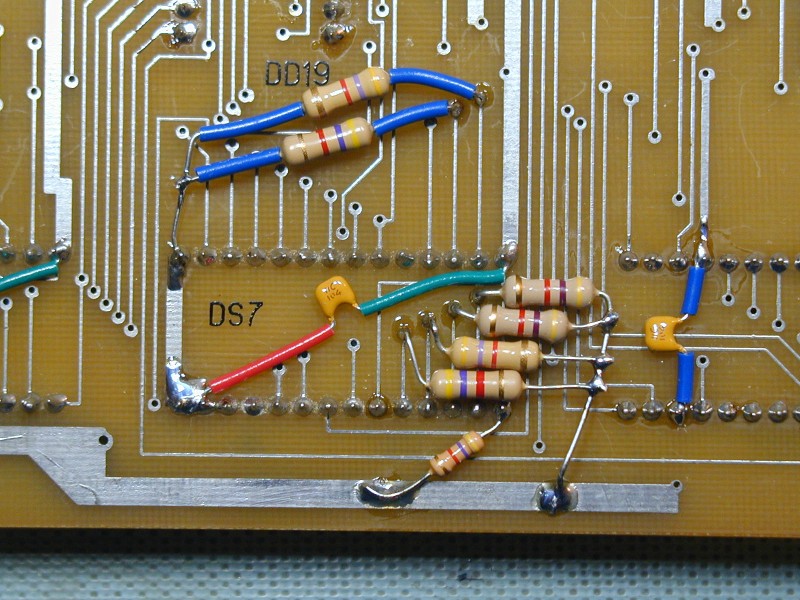
I had been told that the TI-5 used the same CPU board as the TI-3 with a few small mods. The TI-5 populated the MIDI components and added MIDI In/Out/Thru jacks. Since the pcb has locations for the MIDI components, it was easy to install them. I used a 6N138 opto-isolator, which has inputs on pins 2,3 instead of 1,2. Also, pin 5 is gnd, and pin 4 is NC. I modified the connections to DD34 to use the 6N138. I added a 1K pullup resistor from pin 6 of DD34 to +5V, and the 6N138 requires a 4.7K resistor from pin 7 to gnd. You can see both of these resistors in the photo of the bottom of the board. I also moved VD9 to connect directly to the pins of DD34, as this is the typical location for this diode in MIDI circuits. I did not populate the MIDI thru components. Only the inner pins on connector XS9 are needed. I also installed an IC socket and an 8251A chip at location DD27. Here are photos showing the opto-isolator components and mods:
The 8080 CPU requires interrupt vectors to be placed on the data bus after an interrupt. The TI-3 did not use interrupts, so no vectors were needed. I added 4.7K pullup resistors from D1-D7 to +5V on the bottom of the pcb so that the interrupt vectors would be correct. On my board, a 4.7K pullup resistor had already been added from XS4 pin 1 to +5V, so I didn't add a pullup on D0.
I also added 0.1 uF ceramic power supply bypass capacitors between +5V and gnd on the three EPROMs, the two SRAMs, the CPU, and the 8253 and 8251 chips. I am now running the TI-5 code in my unit and so far it seems to be working fine. I can play notes using MIDI in, and can send MIDI messages out when keys are pressed as well. More testing is needed. I was originally using the factory TI-5 EPROM images for DS6,7,and 8, but I found a small bug having to do with the default MIDI channel setting when the SRAM checksum test fails. It was possible to get strange behavior by sending Note On/Off to the TI-5 on channels other than 1 in this case. I have fixed the bug by changing one byte in the DS6 EPROM. DS7 and DS8 are not changed. Here is an archive containing all three TI-5 code images.
Using simulation to understand the firmware:
Running a Verilog model of a synthesizer is a great way to learn how the code works. It's actually not that difficult to create, if the schematic is available. My TI-3/5 model simulates the CPU, memories, timers, UART, switches, keys, LEDs and S&H circuits, so the input is (virtual) switches and keys and the output is timer waveforms and control voltages. I can watch any RAM location to see when it is read or written and what its contents are. When I wanted to see where the keyboard split point was stored in RAM, for example, I set up a simulation to press "Edit", then "Split Pointe", then the F3 keyboard key. I could see in the simulation that the Split Point switch LED turned off when I hit the key, as in the real TI-5. So where did it put the value? I had discovered that the TI-5 code stores keys using their MIDI note numbers. The low C key is 30h (48 decimal) and middle C would be 48h, which is 48 plus 24, in hex. I set a cursor at the place where I pressed the key in the simulation, and started looking at locations in DS13/14 SRAM to find something that looked like setting the split point. Here is how the simulator waveform window looks (RAM addresses are on the left side):
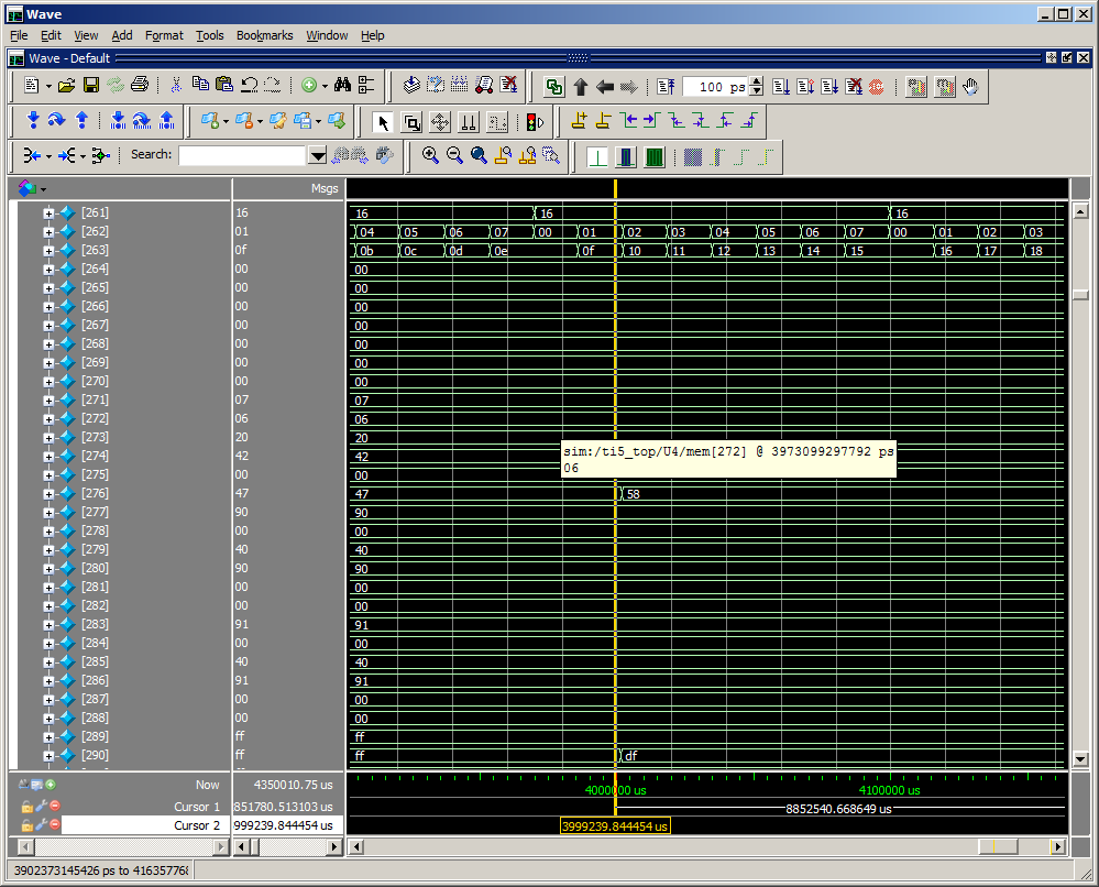
Please ignore the pop-up info window just above the "58". At location 276 in the RAM, I noticed the value was changing from 47h to 58h. 47h is the B key just below middle C. And 58h is the E3 key just below the one I pressed to set the split point. So this must be the RAM location of the split point. 276 is 0114h in hex, and the RAM starts at 4000h in the CPU memory space, so the CPU address would be 04114h for this variable. Now that we know this, we can look at the code and see where this location is being read or written and add comments that this is the split point variable. This same idea can be used to figure out the other data structures used to control the synthesizer.
TI-3 and TI-5 source code listings:
Here is an archive containing the TI-3 and TI-5 EPROMs, disassembled into instructions, with my comments added. The TI-3 code is much better commented than the TI-5. I have not figured out everything, but a lot of it is now documented in case anyone is curious. These files are valid input for TASM32 assembler using 8080 mode. The command line to assemble each file is added as a comment at the top of the file. The TI-3 file has some defines which can be used to enable my bug fixes. If they are all commented out, the binary image will match the EPROM exactly. The TI-5 DS6 file has one define which fixes a small bug having to do with MIDI channel initialization. You can search for the define in the code to see how the bug is fixed. I don't plan to do any more work on either the TI-3 or the TI-5 code.
TI-5 new firmware:
I have been working on the TI-5 code a little more recently, trying to understand it. In the process, I found a few typos/bugs. Most of these were simple to fix. The MIDI clocking speed issue was a little more involved. Anyway, here are new EPROM images for DS6 and DS8 with the changes. DS7 was not changed. Please contact me if you have a working RMIF TI-5 as I would like to have someone that I can discuss this synth with.
Diagnostic EPROM for TI-3 or TI-5:
I thought it would be a good idea to see if the SRAM chips in my TI-5 are OK, so I made a little diagnostic EPROM that can be used to test the RAMs, checksum the EPROMs, test the 8253 system timer, ADC, and DAC. Of course there are many other things that can cause problems in a synthesizer, but this should be better than nothing. Here is the diagnostic EPROM image and some instructions for using it.
DISCLAIMER: I take no responsibility whatsoever for the use and/or implementation thereof, or the misuse leading to damage to equipment, property, or life, caused by the above information. Use it at your own risk.