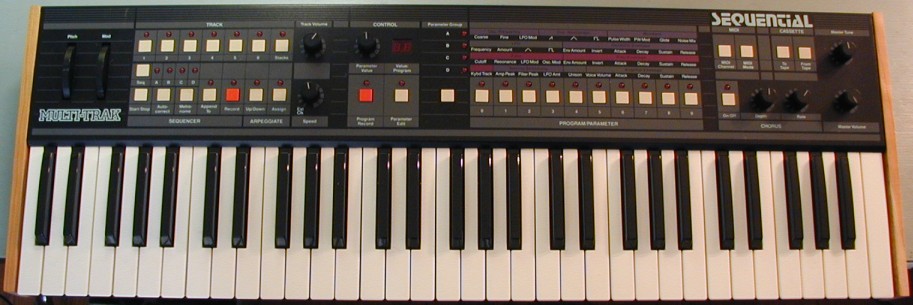
Sequential Circuits/SCI Multi-Trak Page
Background:
Last year it was brought to my attention that the Multi-Trak didn't support CC parameter changes over MIDI. This seems a little odd, since the Six Track and the Max both have this feature, but possibly SCI at the time didn't feel it would get much use, or maybe they just didn't have room in the EPROM for the code. Since I had some familiarity with similar code in the SCI Max from another project, I decided to see if I could add this feature to the Multi-Trak. I also wanted to put the factory patches in the EPROM, so they could be restored easily if lost.
I created a Verilog simulation of the Multi-Trak which allows me to press (virtual) keys or switches, receive MIDI messages, etc, and watch how the code reacts. I can see the pitch, VCA setting, VCF setting, etc of each voice. Basically anything I want to see anywhere in the synth, including inside the combo chip or the Z80. This has been very useful for learning how the code works, what RAM locations store what values, etc.
New Code Features:
I now have a new version of the code, which I am calling V2.3, that has the following features:
Supports CC control of the following parameters: (The CC codes were chosen to match the Six-Track so that existing control software could be used)
;2 Osc Coarse Freq
;3 Osc Fine Freq
;4 Osc Glide Rate
;5 Osc LFO Amount
;6 Osc Env Amount
;7 Osc Env Invert En/Dis
;8 Osc Env Attack
;9 Osc Env Decay
;10 Osc Env Sustain
;11 Osc Env Release
;12 Osc Saw Wave En/Dis
;13 Osc Tri Wave En/Dis
;14 Osc Pulse Wave En/Dis
;15 Osc Pulse Width
;16 Osc PW LFO Mod En/Dis
;17 LFO frequency
;18 LFO amount
;19 LFO Triangle/Square Wave Sel
;20 Noise mix
;21 Filter cutoff
;22 Filter resonance
;23 Filter Env Amount
;24 Filter Env Invert En/Dis
;25 Filter Env Attack
;26 Filter Env Decay
;27 Filter Env Sustain
;28 Filter Env Release
;29 Filter LFO Mod En/Dis
;30 Filter keyboard tracking Amt
;31 Filter Triangle Mod Amt
;32 Amp Env Attack
;33 Amp Env Decay
;34 Amp Env Sustain
;35 Amp Env Release
;37 Unison En/Dis
The Six-Track does not have these, so I assigned them myself:
;40 LFO Vel Sens Set
;41 Filter Vel Sens Set
;42 VCA Vel Sens Set
;43 Osc Env Scale Set
The Osc Env Scale Set CC was added at the request of Ryan (AKA plutoniq9). He wanted a way to increase the effect of the oscillator envelope. There are 5 settings for this:
0-15: Same scale factor as the SCI code
16-31: Osc env has 2X the effect of the SCI code
32-47: Osc env has 4X the effect of the SCI code
48-63: Osc env has 8X the effect of the SCI code
64-79: Osc env has 16X the effect of the SCI code
80-127: Mapped in the code to a value of 64.
When the Multi-Trak power is cycled, this parameter is reset to 0 (SCI scale factor).
Note: If your Multi-Trak already has V3.0 code, then it also has a different SRAM configuration and a slightly different memory map. My V2.3 code WILL NOT WORK with this version of the Multi-Trak. It is possible that this version was only sold in Europe and Japan, as all of the ones I have seen here in the USA were V2.2 or older. Someone sent me a binary image of the V3.0 code, which I have examined (thanks). The changes are only related to the additional SRAM. Code was added to detect the amount of installed SRAM, instead of assuming a fixed amount. The UART was moved to a higher address to allow for more SRAM. I have a new version (3.1) of my code with CC support which has been tested in several of these units. Note that this mod will only work if only the factory 16K (two 6264 chips) of SRAM is installed, otherwise there will be a conflict between the extra RAM chips and the larger EPROM needed for the new code. If interested, please contact me.
Performing the mod:
Here is a set of step-by-step instructions for modifying your unit. Please look it over before attempting the mod to make sure you feel comfortable performing the necessary steps. Please note that the gray flex cables between the power supply board and the digital board are rather fragile. It doesn't take much bending for wires to start breaking.
Since both the Max and the Multi-Trak used a 27128, which is almost exactly the same pinout as a 27C256, doubling the amount of available code space is not difficult. The Multi-Trak makes it even easier, as the third decoded chip select from the combo chip is unused and available.
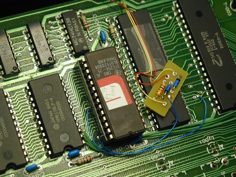
To perform the mod, you need to replace the 27128 with a 27C256 EPROM, and connect two pins on that EPROM to points in the circuit that do not route to the EPROM socket. The easiest way to do this is to use a second IC socket, with two pins bent out, plugged into the SCI IC socket for the EPROM. One of the bent-out pins connects to A15 at the Z80. The other one connects to an OR of the original EPROM chip select and the spare decoded chip select. Both of these signals come from the Combo chip. To OR the two signals into one, I use two schottky diodes and a 1K pullup resistor. I used a small pc bd that holds the two diodes and resistor for a neater job. I attached this board to the top of the Z80 with double-stick foam. Here is how the mod looks with the extra socket and the little pc bd in place: (the green wires are an SCI factory mod that many units have)
Here is a document that explains the new code features and how to use them.
Other Misc Multi-Trak Related Information:
Here is a zip archive that contains MIDI sysex files for both A and B versions (almost) of the Multi-Trak Factory Programs. I found the A version file on the web. (Thanks) I created the B version by manually copying each program from their A location to their B location. There are some sounds in the factory B version that do not exist in A. I did not have the programming parameters for those, so I placed the sounds that were in A, but not in B in those spots instead. Here is a list that shows the program numbers for the (almost) B version. I read out the sysex data and wrote it to a file using a program called MIDI-OX.
Here is a binary image of the OS EPROM from my two units. They are serial numbers 00294 (Rev A bds) and 01766 (Rev B bds) The EPROM contents were the same. The EPROM was labeled "(c) 1985 SCI Mult-2-2" The checksum is 0x0FE8. The EPROM is HN4827128G-30. A 27C256 EPROM can also be used. Just put the image in the top half of the EPROM, as A14 will be tied high by the connections on the pc bd.
Both of my units had the battery drain problem, or roughly 220 uA battery current when power was off. I applied the fix found elsewhere on the web, and the off currents went to 1 uA for one unit and 3.5 uA for the other. Both of these are low enough to give long battery life.
The newer of my units had three extra components added on top of the board near the keyboard MCU. The components were a 10 uF tantalum cap, a 1N4148 diode, and a 200K resistor. The trace to pin 6 of the MCU was cut and these components were used instead to generate a power-up reset to the chip. The older unit did not have this fix, and I didn't noticed any problems with the keyboard MCU reset function on this unit, but I modified it to match the newer unit anyway.
Comparing the traces on a Rev A vs Rev B Bd2, I noticed that on Rev B, the trace that approaches pin 7 of U208, which is tied to gnd, stops short of pin 7 and does not connect to it. This is a ground trace that was meant to prevent coupling. On the Rev A Bd2 artwork, this trace connected to pin 7 of U208, shorting it to ground. This is an output from the counter, so I am sure it was not meant to be shorted to ground. I cut this trace right next to pin 7 of U208, to match the Rev B artwork.
The newer unit had a rev B analog board in it, but also had the mod for hum that's mentioned in the service manual applied to it. This mod involves making a number of cuts to traces on the board, and adding some resistors, caps, and a jumper. I guess this mod was developed after the Rev B analog board was laid out. I applied this mod to the older rev A PC bd.
My older unit also had two 1K 1/4W resistors soldered from the two center terminals of the main DPDT power rocker switch to chassis ground. The newer unit had these as well, but they had been incorporated into the artwork, and were hooked to the "off" terminals of the DPDT power switch, as shown in the schematic. I moved the resistors in the older unit so that they matched the newer one and the schematic. I am guessing that the purpose was to ground the front panel when the unit is off, in case of an ESD event. Not sure about this. Anyway, it seems that they belong there.
It seems that the 15V back-panel rating for the external transformer may be more like the minimum value. If I feed in 14.90VAC instead of the rated 15VAC, I start to see 120 Hz pulses on the -6.5V supply, and I can notice a slight hum on the output of the synthesizer, which gets louder if the voltage is lowered. (This test was done after installing new capacitors for C101 and C102) The hum and pulses are pretty much gone when I feed in exactly 15.0 VAC. (or higher) The +5VA supply is clean even with the lower supply voltage, which makes sense, as it is has 1.5V more "headroom" than the -6.5V supply. With 14.9VAC input, the -6.5V supply starts dropping out on the dips of the 120 Hz ripple on C102. I am thinking that a low-dropout regulator or maybe just a larger capacitor here would fix the problem. I would guess that even though the power jack is labeled 15VAC at 1.25A, probably the original supply put out more like 15.5VAC at the current drawn by the Multi-Trak. (Feeding in too much voltage could cause overheating of the regulators, and possibly damage other things as well.) I have designed a nominal 15VAC circuit using two (easy to obtain) 18VAC transformers. It seems to work OK with both of my units, and puts out 16VAC with no load, and 15.3VAC when powering the synthesizer. I can't hear any hum when using it. Here is the schematic. Note that both the Multi-Trak and the Tom Drum used the same E-170 power supply, so this should work with the Sequential Tom Drum as well, although I have never tried it. Actually, since building that circuit, I was informed of a much easier way to make a power supply for the Multi-Trak. If you can get a Colorado Memory Systems AC adapter Model 910-002 WA2T2500NCT, it puts out 16VAC at 2.5A and has a center tap. You just need to put a new connector on the end that connects to the Multi-Trak. This is what I am currently using. Bought one on a popular auction site for less than $20.
Here is some information on the SCI Combo Chip I-602 used in the Multi-Trak, and also in the SCI MAX.