Emulating a Vacuum-Flourescent Display with an LCD
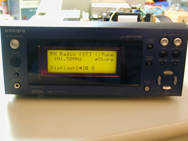
Someone recently presented me with an Onkyo/Integra NAC-23 network-connected audio device. This device used a Samsung 20S401DA2 4x20 vacuum-flourescent display, which unfortunately had stopped working. After a quick search on the web did not turn up any source for a replacement, and attempts to troubleshoot mine without a schematic failed, I decided to try emulating the display with a more standard 4x20 backlit LCD module. This required inserting a small circuit between the NAC-23 and the new display module, to translate the VFD commands into those used by the LCD module. I decided to use a PIC micro-controller for the translation. The NAC-23 monitors a busy signal from the VFD module, and (theoretically) does not send new commands or data until the module is not busy. I decided to implement the busy signal and the input data register in hardware as I wasn't sure the PIC could respond quickly enough. While the commands used by the two modules are completely different, both modules use ASCII codes for standard characters, so no translation of these was necessary. The VFD module has storage for 16 user-defined special characters, whereas the LCD module only has space for 8. I stored all user-defined characters in the PIC's RAM, and sent them to the LCD module as they were placed on the screen, with the hope that only eight or less would be needed at any one time. This seems to have worked out OK, as you can see from the photo at the top of this page. In initial testing I discovered that the NAC-23 seemed to be sending characters even when busy was asserted, if the PIC/LCD module stayed busy for too long. I made a change to the code so that after it finishes processing each character, it checks to see if the data register contents have changed since the last character was accepted. If so, then we assume that a character has come in while we were asserting the busy signal and process it. Adding this seems to have fixed the occasional dropping of characters.
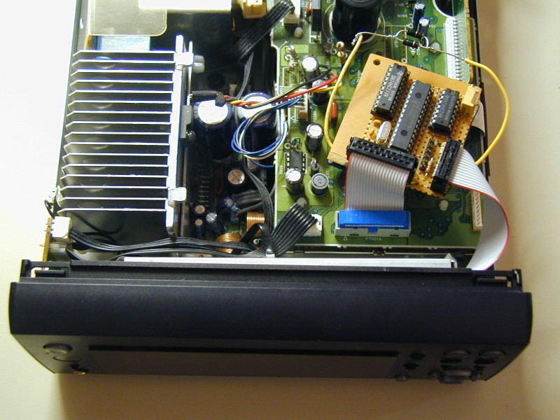
Here is a photo showing the translation circuit attached to the Integra NAC-23: (I hand-wired the circuit on a perfboard, since this is a one-off project)
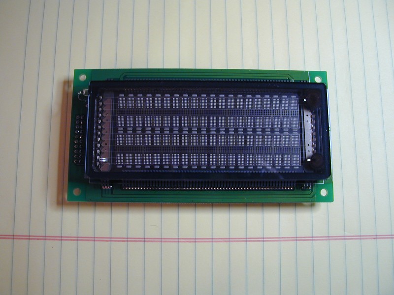
Here is a picture of the non-working VFD module: (The step-up circuit that generates the high voltage needed by the display has failed and draws well over an amp. The rated 5V current for this module is ~750 mA)
And finally, here is a link to a schematic of my interface circuit: (If anyone has a use for the PIC translation code, please contact me)