Mono/Poly Mayhem
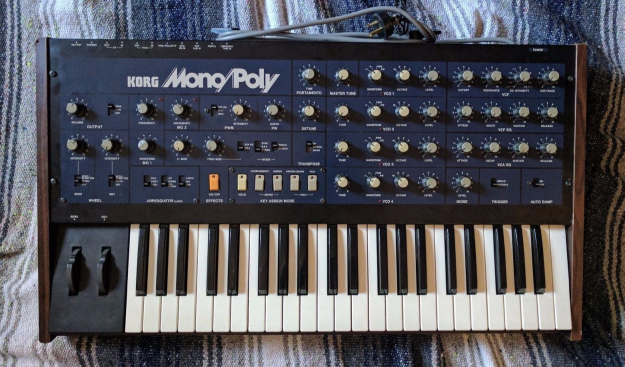
Since I already own a PolySix, it seemed logical to get a Mono/Poly to go with it. When one appeared on a famous auction site recently at a lower-than-usual Buy It Now price, I grabbed it. The ad mentioned that a tech had looked it over and that it needed "expensive troubleshooting". Silly me for simply taking someone else's word for it. What this synthesizer actually needed was all four (!) SSM2033 VCO chips, an SSM2044 VCF chip, an 8049C-217 key assigner MCU, three 4000-series IC's, an op amp, a 2SC1345 transistor, and a 1M pot instead of the 10K one someone had installed. Wow! (I have checked the power supply and it seems fine. No sign of over-voltage, or spikes) OK, now what? Luckily I had the filter and MCU chips here from previous projects, so those were not a big deal. But SSM2033's are $85-130 each, if you can find them. I didn't really want to spend another $500, so I started studying the SSM2033 chip data sheet and thinking about whether it was possible to replace it with something else. I noticed that in the Mono/Poly, Korg had added two pc boards late in the design process:
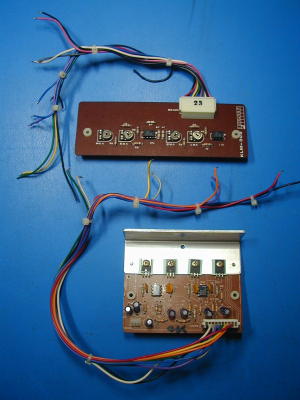
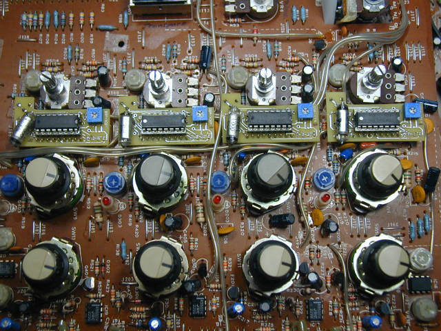
The SSM2033 contains a summing op amp which adds the currents from the various frequency control sources, such as octave, modulation, note selection, etc. Apparently this op amp has some sort of drift or offset issue, as Korg decided not to use it, and instead used the four op amps on the upper pcb in the photo. The SSM2033 has a circuit that heats the internal die to 85 degrees C and holds it at that temperature to reduce drift due to temperature changes. Apparently Korg decided that the internal heating alone was not enough, so they added 475 ohm resistors, cemented to the top of the four chips, and ran current through them to act as heaters. The lower board in the photo senses the internal heater current of each 2033 chip, and uses it to control the current through the external heating resistors, so the chip is heated inside and outside. I disconnected and removed these boards, since they were specific to the SSM2033.
My first thought was to use a circuit based on an LM3046 transistor array, some op amps, and some resistors, to emulate the 2033. The Moog Prodigy uses one of the transistors in the 3046 as a heater to stabilize the die temperature, similar to how the 2033 works. But then I realized that there was already a chip with all of the features of the SSM2033, including the triangle converter, temperature compensation, pulse width control, etc. The CEM3340. I started comparing the data sheets, and it seemed that emulating the 2033 with a 3340 might be possible with only a small number of external components. Here is my proof-of-concept implementation:
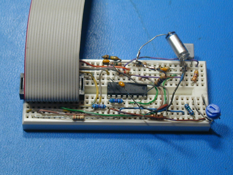
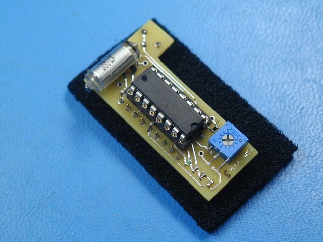
I installed machined-pin IC sockets for all four of the 2033 chips, so that I could plug the DIP cable in for testing. (These sockets are also needed for the final version) Here is how the pcb looked with the new sockets installed:
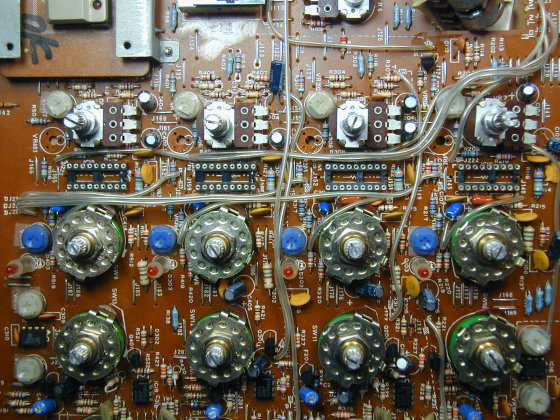
The prototype seemed to be working well enough, so I decided to lay out a pc board. The goal was to fit it in the space where the 2033 chips had been. It quickly became apparent that I would need to use SMD resistors to get everything to fit. The main oscillator capacitor needs to be low drift, so I wanted that to be through-hole. My circuit would have a volts/octave (scale) trimpot, which would be impossible to adjust, since it would be between the pcb and the front panel. Luckily, the equivalent trimmer for the SSM chip is right next to the chip, so by removing it, making my board L-shaped, and placing my trimmer on the bottom of the board, I was able to place it right where the old trimmer was, so it lines up with the hole in the pcb. (Luckily, all four oscillators had the trimmer in the same position) You can see in the above photo that the original trimmers have been removed. There is a second trimmer on my board, but it's not something that will need adjusting and is more or less optional. Here is how my plug-in SSM2033 replacements look so far:
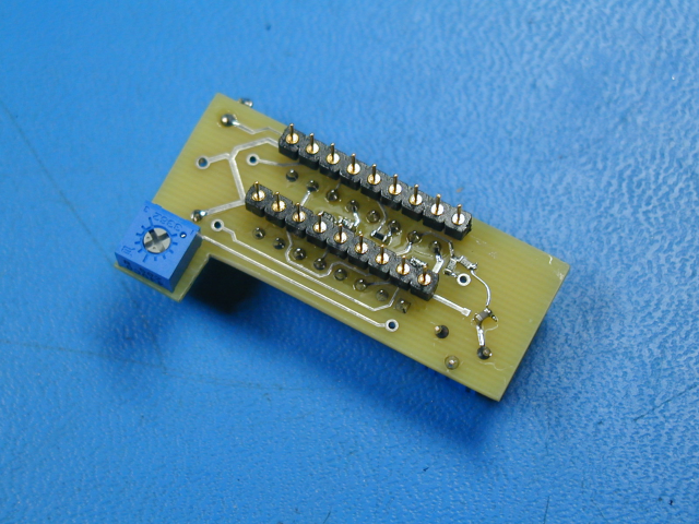
As you can see there are a number of 0603 SMT resistors, on both sides of the board, and a few capacitors as well. I laid out the board for a specific mica through-hole capacitor, but used some polystyrene capacitors which I had on hand. Both of these are low drift types. The Mono/Poly used polypropylene caps, which are also stable with temperature. Here is how the boards look when installed:
But how does it work? How does it sound? I am still in the process of fine-tuning the design. Getting it working was not too hard, but a few small issues have cropped up which I have been working to resolve. There are some details which the data sheet does not really mention. I did compare the sound with a friend's Mono/Poly and decided that we couldn't really notice a difference in the oscillator sounds.
A change of direction:
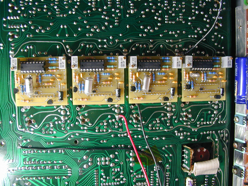
The SMD implementation was a good starting point, but I decided I wanted to use 10-turn pots and have better access to the high-freq tracking one. Also, a through-hole version would be easier for many people to build, in case that becomes important. So I laid out a (mostly) through- hole version, with a few small tweaks to the design. I ended up adding an op amp to buffer the pw adjust voltage, and decided to use an SMT one, as the layout was pretty much finished, and I didn't want to make the board any larger. I removed the sockets from the top, and mounted them on the bottom instead. Here is how the through-hole boards look:
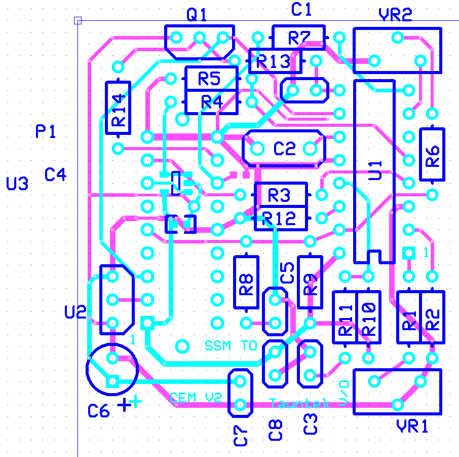
Here is the schematic of the second (through-hole) version of the circuit. Note that some resistors need to be removed from the Mono/Poly board to use it. These are indicated on the schematic. This version was designed to mount on the bottom side of the board, for easier access. Here is a component placement drawing. (The polystyrene caps that I used don't really fit in the space on the pcb, but I wanted to use them anyway to get the best stability.) I have concluded that the CEM3340 VCO chip has more temperature-related drift than I expected. From a cold start, it takes about 20-25 minutes of operation for the oscillators to stabilize. During that time, they drift down in pitch by 30-50 cents. After that they tend to be pretty stable. So best to wait 1/2 hour before calibrating them, as the manual suggests. I may work a little more on trying to eliminate the drift.
It should be possible to mix SSM2033 chips and CEM modules in the same Mono/Poly. Only the voices using the CEM module would be modified to support it.
Please note: Taking a Mono/Poly apart and replacing chips must be done carefully, or damage to the synthesizer could result. It should only be attempted by someone familiar with this type of work. I will not be responsible for any damage to any instrument caused by either proper or improper use of the information offered here.