Replacing SAD-512 BBD chips in an ARP OMNI-2 Chorus Board
I was recently helping someone repair an ARP OMNI-2. At first it seemed that only one of the three Reticon SAD-512 chips was not working on the chorus/phaser board, but later we lost all output from the strings section and found that all three chips had failed. These are getting to be hard to find, so we were thinking that it would be nice to see if a different BBD chip could be used instead. The SAD-512 is a 512-stage chip that operates from ground and a positive supply voltage. Those two specs alone reduce the number of possible replacement chips. After some research into the relative availability of different BBD chips, I settled on the MN3204, which has 512 stages and operates on a positive supply voltage. The MN3204 was designed for a lower maximum operating voltage, maybe for use in pedals powered by a 9V battery. Also, the maximum clock frequency is lower than for the SAD chip, but it's higher than required by the OMNI-2. Aside from that, the specs seemed similar to the SAD-512. I drew up a schematic using a CD4050 to level-shift the 0-15V clock inputs to the chip to 0-9V signals. A simple 78L09 regulates the +15 input to +9V for the BBD chip and the CD4050. Here is the schematic.
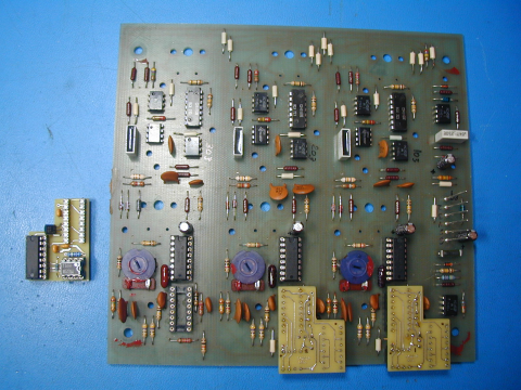
At first I was planning to hand-wire three circuits, but decided to lay out a small pcb for better long-term reliability. I put machined-pin IC sockets on the ARP pcb to accept the round gold headers on my adapter board. This adds some cost but allows unplugging the adapter board if needed. The BBD and 4050 chips are socketed and mounted on the underside of the board, to fit into unused space on the ARP board. I was concerned about clearance issues and wanted to stay as close as possible to the height of the original components. (Having these chips mounted on the bottom of the pc board likely makes it unusable in most other devices that used the SAD-512) Here is how the boards look in place:

The chorus board has a voltage divider on pin 3 of op amp Z1 which sets the DC bias for the low-level AC signals inside the BBD chips. I left the 182K resistor alone and reduced the lower resistor to get about 4.5VDC at the output of Z1, since the BBD chips are being operated at 9V now. A trimmer could be used here to adjust for symmetrical clipping with a sine wave input, or for minimum distortion.
We did a quick comparison in an OMNI-2 of this board against one with the SAD chips installed, and did not notice any difference in the sound. We did not do extensive testing.
Please note: Taking an ARP OMNI apart and replacing chips must be done carefully, or damage to the synthesizer could result. It should only be attempted by someone familiar with this type of work. I will not be responsible for any damage to any instrument caused by either proper or improper use of the information offered here.