My PPG wave 2.3 page

I recently volunteered to help someone repair their PPG Wave 2.3 synth. It seemed that the service manual info on the PROZ board was not as good as for the other boards, so I decided to redraw the schematics for just that board and offer them here.
Here is an archive containing my V2.3 PROZ board schematics. There may be mistakes, so use them at your own risk.
I thought it might be helpful to capture some waveforms showing the timing sequence created by the PALs. The A,B,C,D and H inputs to the PALs come from two S163 counters, and are decoded to enable specific signals at specific times. Some signals are active pretty much all the time, while others may only be active when the CPU accesses DRAM, or a sampled waveform is being played. Anyway, here is one of the PAL waveform captures, and here is a zoomed in version. Both were captured while a key was pressed.
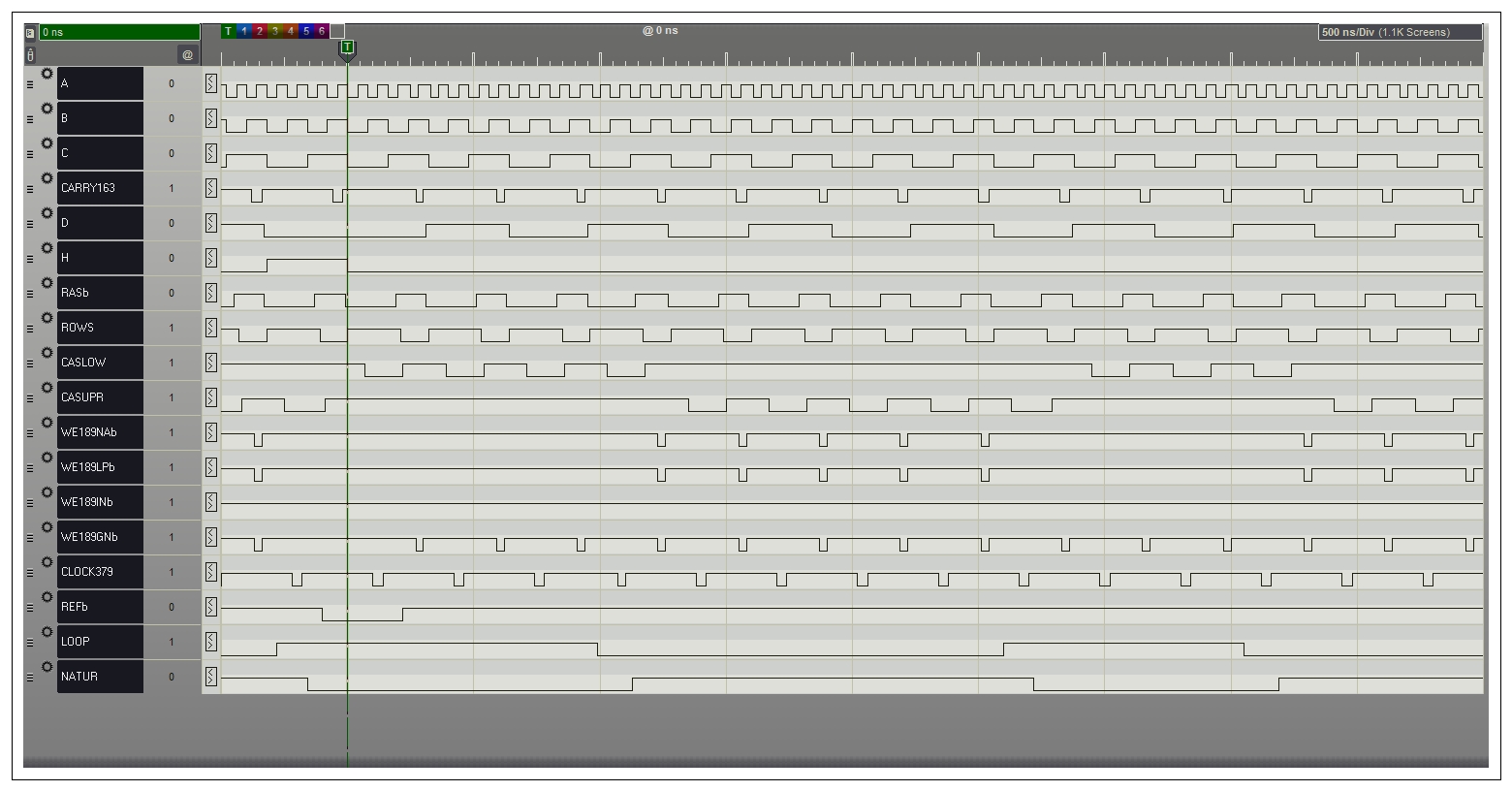
PPG Wave 2.3 Voice Board Test Fixture:
Some features of the voice board would be difficult to test using the synthesizer firmware, so I decided to design a small test fixture to exercise the voice board outside of the synth. The hardware design is very simple, just a PIC microcontroller, eight pushbuttons to select a particular test, and two dual- DAC chips to drive the three CV's. A decoder chip is used to create eight chip enables as well. I used a current-limited bench power supply to provide +/-12V and +5, and did not include any circuitry for those.
Here is an archive containing a schematic and the PIC code for my voice board test fixture. Use these at your own risk.
Here is a photo of the fixture connected to a voice board:

Despite the simplicity of the design, there is still a fair amount of wiring required to hook everything up:
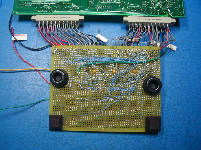
For this type of wiring I use 30 gauge solid core "wire-wrap" wire, as it is much easier to solder in tight places than stranded wire. The 8 pushbuttons select one of seven specific tests, or idle mode. The first test creates a 12-bit ramp on a particular channel's waveform DAC. Here is how it should look:
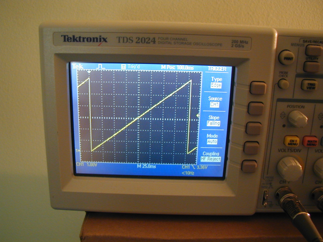
This is the waveform at the output of the op amp fed by the DAC. Once the waveform goes through the filter it will look very different. The frequency of this ramp is around 1 Hz, so even passing it through a coupling capacitor will change it significantly. The amplitude of the ramp is about 6 volts peak- to- peak, and since there are about 4000 steps, each step corresponds to about 1.5 mV. So it's impossible to evaluate the linearity of the DAC using an image like this, but it can indicate whether the DAC appears to be working correctly.
Another test applies a ramp to the VCA control voltage. The photo below shows the output of the voice board for one channel while the VCA ramp is applied. For this test, the waveform DAC is fed with a ~1 KHz square wave.
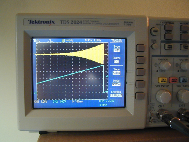
We can see that although the ramp goes from 0 to about 3.5 volts, the VCA is only turned on when the ramp voltage is above about 1.8 volts. This is determined by the design of the voice board and how the VCA is used by the Wave 2.3 firmware.
The test fixture plus voice board currents were +5V: 100-140 mA, +12V: 115 mA, -12V: 100mA . I set the current limiting on my power supply to 150 mA for each supply. This can help limit damage if there is a short somewhere, or a wiring error. The current will vary a little depending on which test is running.
Repairing PROZ and Voice boards from a PPG Wave 2.3:
Just thought I would add a few observations on repairing these boards. For one thing, the voice board schematics available on the web did not match the boards I was working on. In several places, the connections had been changed to ease the pcb layout. Voice board IC59 D and Q pin connections are quite different from what the schematic shows. The function is not changed, just which flip flops are used for which channel. IC64 is another example. The A output is pin 14, B is pin 1, C is pin 7, and D is pin 8. This can be confusing if you assume that the schematics are 100% accurate.
I worked on the PROZ board by itself, out of the synth, for better access. To help with this, I made a small test fixture with a PIC chip, which wrote known values to registers on the PROZ board. The PROZ board draws about 3.2 amps from a 5 volt power supply. I set the current limiting on my bench power supply to 3.35 amps, although at that level, there is still plenty of current available to damage parts if something goes wrong. The main problems with the PROZ board ended up being the pcb itself, not the IC's. The traces in the area of the DRAMs are pretty fine, and several of them had broken right next to the pin of a DRAM IC socket. The breaks isolated a number of DRAMs from several address lines, scrambling the played waveforms. If you suspect this type of issue, just use a DMM in continuity test mode to check the address signals from the DRAM address mux to every DRAM chip. I suggest checking the data connections to the DRAMs as well. (Actually, two of the DRAMs had been found earlier to be defective and replaced, but the problems remained) The board I was working on also had a small break in a trace in a different area of the board. This was in the vicinity of a previous repair, which made it easier to spot.
Here is the small test fixture I made for the PROZ board:

Here is an archive containing the schematic and PIC source code for the PROZ board test fixture. Use these at your own risk. A latch is used to drive the LEDs because the PIC doesn't have enough pins to drive everything directly.
The four LEDs show which of the 16 tests is currently running. Selecting a test causes values to be written to registers on the PROZ board, then a scope can be used to check the result. With 16 tests, I was able to check each bit of the frequency section increment value. And with the same 16 tests I also wrote to registers in the PWN section to check some things. The PROZ board is constantly cycling through 16 channels for the 16 oscillators. This makes testing more complicated. By isolating four pins of one of the socketed 74S163 chips, and then driving these signals with the PIC, I was able to select just one channel all the time for easier testing. The left switch on the fixture steps through the channels and the right switch selects the test being run. The channel selection is applied to the PROZ board using the four small clip leads. I did not have the correct DIN connector for the PROZ board, so I used parts of two connectors instead.