A low-cost MIDI interface for the Korg Poly61 Synthesizer
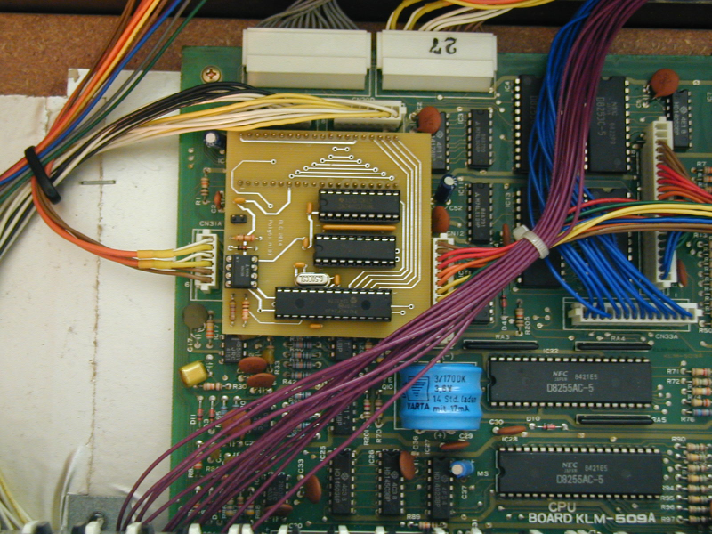
I recently purchased a Korg PolySix and wanted to add MIDI to it. There are several options available on the web but I wanted to design my own as a learning exercise. I decided to make it plug in as a replacement for the key assigner MCU, so that it could also be used to repair a synth with a bad MCU chip. I felt that all I really needed was Note On/Off, but later decided to add MIDI arpeggiator clocking as well. After I got it working, a friend mentioned that the Poly61 used the same key assigner CPU, so I decided to try my design in that synth as well. I wanted to use through-hole components to make it easier for people to build, which meant that the board would be larger than the 40-pin DIP key assigner and would sit over other components on the Korg PCB. The physical layout of my pcb was geared toward the PolySix, so it was a little tough to get it installed, but I did, and it worked fine in the Poly61 too. So I made a new pcb just for the Poly61. Specifically, it can fit on a KLM-509 pc board, and replace the key assigner CPU, which is either 8049C 384 or 8049C 217 (also used in the PolySix). Here is how it looks installed in a Poly61. (the MIDI cable is not attached but you can see the two-pin connector for it)

Here is a copy of the schematic. The PIC performs the key assigner function and also interprets MIDI commands to press and release keys. Local keys can be played at the same time, up to a total of six notes, including any MIDI notes. MIDI channel can be set by holding one key down while powering up the Poly61. Low C selects channel 1, C# channel 2, etc. The 17th key selects OMNI mode. Arpeggiator clocking can be set the same way, using keys starting at middle C. Middle C selects local arp clocking (not MIDI, also the default setting). C# selects quarter note clocking, D selects eighth note, D# selects sixteenth note, and E selects thirty-second note arp clocking. The top six keys can be used to set the MIDI note number that maps to the bottom key. Holding the top key at power-up sets the note number to press the bottom key to 60. The next key down selects 48. The next key selects 36, etc. 36 would probably be the "normal" setting. The MIDI channel, MIDI note range, and arp clocking settings are retained until set to different values using the same method.
Please note: This interface does not allow saving, changing, editing, or restoring patches, or doing anything other than playing notes and clocking the arpeggiator over MIDI. It should only be assembled and installed by someone with an adequate understanding of electronics. If it is assembled or installed incorrectly damage to the Poly61 circuitry could result. I will not be responsible for any damage to any instrument caused by either proper or improper use of the design presented here.
I am offering pc bds for $30 each (plus S&H) and programmed PIC chips for $7 each. Please contact me if you are interested. I will not offer assembled boards. You will need to order the other parts yourself and put it together. Do not attempt this unless you have decent soldering skills. Here is a parts list for the interface.
Since the board is heavier than the original chip, and larger as well, you will probably want to secure it in some way to keep it from coming unplugged. I have not yet worked out the best way to do that. Probably double-stick foam between the bottom of the pcb and the IC socket would suffice.
If you have a Poly61 that already has Korg's MIDI interface installed, but don't want it to come up in OMNI mode, here are some EPROM binaries which can replace the factory MIDI interface code. Each file selects a different MIDI channel on power up. The MIDI commands to set the channel and enable/disable OMNI mode are still supported in the code. The only change is that it doesn't come up in OMNI mode.
Poly61 Program MCU source code
In case you have always been curious to see the code inside the 8049 (Korg 8049 C 337 MCU) that handles patches, parameters and the DCO's in a Poly61, here is an archive containing a source code listing, and also a binary image of the code. To create this, I dumped the internal ROM binary image, ran it through a disassembler, and then spent lots of time figuring out what the different code and variables do. I have also run a Verilog simulation of the code with an 8049 model and a little bit of hardware around it, which helped in some places.
Redrawn KLM475B schematic:
I decided to take a shot at redrawing the KLM-475B schematic. The KLM-509 is actually very similar, so this schematic should be useful when working on that board as well. Here are the page1 and page2 pdf files.