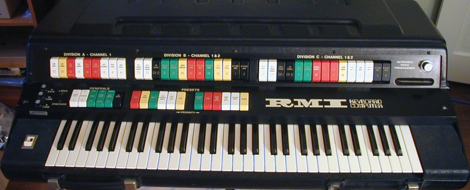
Early waveform playback keyboard: RMI Keyboard Computer (KC) II

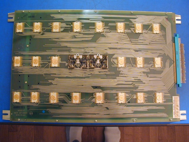
I recently had a chance to work on an RMI Keyboard Computer II. This keyboard was made possible by a late 1960's collaboration between the Allen organ company and Rockwell International, a defense contractor in California. Rockwell had the technology to design and make custom chips, and used it to create the sound generation section of the "MOS organ" for Allen, which was then used by their subsidiary RMI to make the KC I, and KC II. The "MOS board" holds 22 custom chips, all in small (for the day) 42-pin packages. Some of these chips are small ROMs, which hold the waveforms for the preset sounds. Others contain RAM that the selected waveforms are copied into for playback. Others generate the necessary signals for reading out the waveform data. Multiple sounds can be played at the same time. Polyphony is either 12, 6, or 4, depending on the number of waveforms used per voice. Computer punch cards can be used to load up to four custom waveforms into RAM, which can then be played either alone, or in combination with the ROM-based ones. Below is a photo of the pcb that holds the Rockwell custom chips. (the circuitry in the center is four clock drivers/level shifters for the main 1 MHz four-phase clock) The rest of the design used mostly 7400-series logic, with some older DTL chips in a few places, some 4000-series chips and a few op amps. One of the clock drivers on the MOS board had several failed transistors in it. Replacing these parts was a little tricky, as the components in this area are pretty close together. The resistors are all standing on end, like an early transistor radio.

Here are two scans of the "Computer Service Manual" for the KC II. I found this one on the web, and this is my own higher-resolution grayscale scan of a printed copy of the same manual.
The card reader was not working in the unit that I had in for repair, so after I got it going, I wrote up a little description of its operation. Here is that document.
A second RMI Keyboard Computer repair:
The owner of the KC II also had a non-working original Keyboard Computer. This one had a dead -5V power supply. It seemed that the LM305AH was no longer working, so I replaced it and also the 2N2905A. Luckily, these parts can still be found if you look. To test the repair, I applied 10V to the large filter cap with a bench power supply set for 100mA current limit. The supply immediately drew the full 100mA and put out less than a volt. Further testing revealed that the tall white Mallory 500 uF electrolytic cap was shorted, with a resistance of less than 1 ohm. Replacing this cap restored the supply to proper operation.
The card reader on this unit was also not working. The symptoms were a little different from the KC II one. As soon as the card was inserted, the address counter immediately counted up to 16 and shut off the clock. So the clock was not being gated by the pulses from the card. Z6 DTL Quad NAND gate had failed, leaving the J&K inputs to Z8 always high, enabling the counter all the time. Replacing this chip fixed the card reader. BTW: The C.R. voltage on both units was set to about 7.5 volts DC.
Caution: Whenever the MOS pcb is removed from the KC II, you should short all pins of the edge connector together to reduce the risk of ESD damage to the MOS chips. I used 22 ohm resistors on each female connector pin, with the other ends all tied together. I used a 100-pin edge connector, with the necessary 0.1" pin spacing, as it was easy to find.
Please note: Working on a KC II requires a lot of skill and care, or damage to the keyboard could easily result. It should only be attempted by someone with the necessary knowledge, equipment, and experience. I will not be responsible for any damage to any instrument caused by either proper or improper use of the information presented here.