Sequential Circuits/SCI Max Page
Note: As of March, 2019, the cost of the NVRAM used in my MAX upgrade has increased to the point where the project doesn't make sense, so I no longer offer any parts for it. I am leaving the web page here, in case someone finds it interesting.
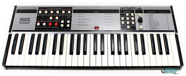
The Sequential Circuits Max was designed as a companion to the Six-Track, Multi-Trak and possibly the C64 personal computer. It relied on MIDI messages for parameter changes, having no on-board way to vary them. It came with 80 "factory sounds" in EPROM, and storage for 20 more in RAM, which could be used after downloading via MIDI. Two "songs" or sequences could be recorded and either stored in RAM or dumped to MIDI. No battery back-up was provided for RAM, so all song data and the 20 programs were lost when the unit was powered down. Sound generation circuitry was almost identical to what was used in the Six-Track.
Recently another synth enthusiast and I became interested in seeing whether we could improve the Max by adding non-volatile storage, more RAM, and a larger EPROM. Unlike the situation in 1985, these things are now readily available at reasonable cost.
Our goals were:
1) Increase the number of downloadable sounds to 100, like the Six-track
2) Switch to battery-backed RAM to preserve sounds and songs with power off
3) Increase the amount of RAM, to increase the number of notes that could be recorded.
4) Try to implement "unison mode" which the Six Track had, but the Max didn't support
5) Add additional factory sounds if possible
In order to accomplish these goals, it was first necessary to understand a lot of the existing Max code, so that the necessary changes could be made. My first approach was to simply run the EPROM binary dump through a disassembler program and try to understand the output. Figuring out the code that talks directly to hardware is not difficult, as the hardware is well documented, and it's pretty easy to see what's going on. But unfortunately, much of the code is only concerned with manipulating internal data structures. Trying to decipher what that code is doing (and why) is not easy. My next approach was to try using a Z80 simulator, and actually running the code to see what it did. There are Z80 simulators available for download on the web, although I should mention that I later learned that the results I was getting were incorrect. The big problem with just running the code in a CPU simulator is that this code relies on values read from hardware. Pressed keys and buttons, MIDI inputs, etc. Without these, the results were not really that interesting. I finally settled on the most involved approach, but also the most powerful. Verilog is a modeling language often used to design integrated circuits. It is C-like, but has many special features for modeling circuitry. Through my work, I have access to a Verilog simulator. I found a Verilog model on the web for the Z80 microprocessor. Using this model as a starting point, I added models for RAM, EPROM, flip flops, analog muxes, decoders, etc, until I had a working model of the entire Max circuit. The trickiest thing to model was the analog "synth on a chip" IC's that are used in the Max, Multi-Trak, and Six Track. It took me a few tries to get it working correctly, but my model now works well enough that I can watch the synthesizer execute the tuning algorithm and save the results in RAM. Getting that working gave me confidence that the rest of my simulation was accurate. I am now able to press virtual "keys" and switches and see voices turn on, monitor their frequencies and waveform, receive MIDI messages and see what code is executed, etc. I can dump RAM at any point in the simulation, or monitor any RAM location(s) that I think might be interesting. Also, as part of this project, I created equivalent Verilog simulations for the Six-Track and Multi-Trak designs as well.
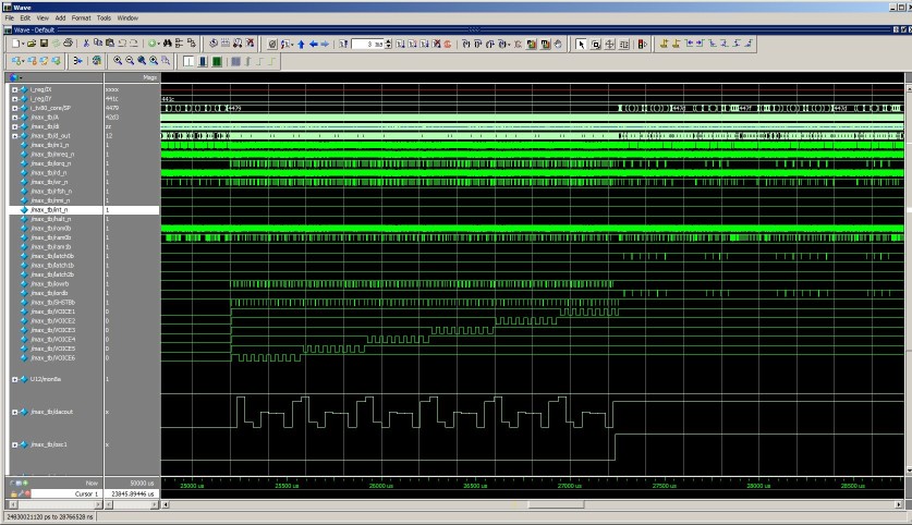
Here is how simulation shows the Max code updating the eight S&H voltages for each of the six voices, which it does every 7 mSec:
(You can see the DAC output at the bottom switching to all of the different voltage levels)
After spending a lot of time running different simulations and adding comments to disassembly listings, I have a new code image that achieves the above goals:
1,2) 100 sounds, all downloadable, located in battery-backed RAM
3) Note storage increased from about 500 to about 3200
4) Unison mode is working now
5) Three sets of 100 factory sounds in EPROM:
a) 80 Max + 20 Six track Unison factory sounds
b) 100 Six Track factory sounds
c) 100 Multi-Trak factory sounds (without chorus or vel sens, of course)
d) CC parm changes to current program can be saved to program 99, then copied to any other program
e) MIDI receive buffer increased from 64 bytes to 128 bytes
f) Removed code that reduced volume of subsequent notes if CC change received while MIDI note with low velocity playing. This seems like some sort of code bug. Not sure what the intent was.
To add these features to an existing Max, it was necessary to upgrade both the EPROM and the type and amount of RAM. The Max shipped with a 128K EPROM and two 2Kx8 SRAM chips. A modified Max has a 256K EPROM and a single 32Kx8 SRAM chip (only 16K is used). To make it easier to perform the modification, I have designed a small PC bd which holds the EPROM and NV SRAM. This board was designed to plug into the existing EPROM socket on the Max. Five additional (short) wires connect from the Max main bd to the new memory board. In addition, the two SRAM chips on the Max main board need to be disabled, as the enables for these chips are used by the new memory. For the more ambitious, it is also possible to perform the upgrade without using the memory pc bd, although it is more difficult.
Here are some photographs that show the Max memory board:
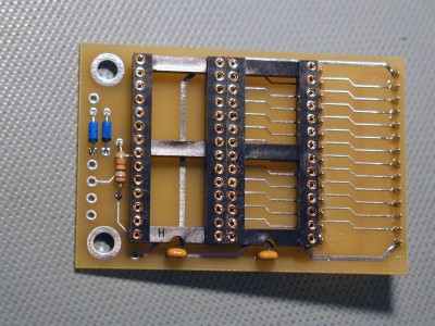
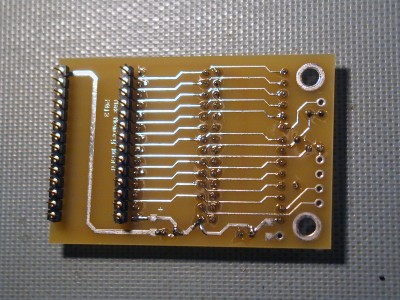
Above photos show board with DIP sockets installed and gold pins on bottom for plugging into EPROM socket on Max pcb. EPROM socket on memory board could be stamped-contact type to save a little money. NVRAM socket should probably be machined-pin type as shown. Mounting holes were added for possible future use.
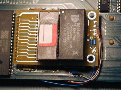
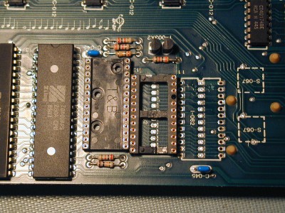
Above left photo shows memory board with EPROM and NVRAM installed, plus five wires which connect to Max main pc bd. Right photo shows Max main bd with EPROM and U112 removed and replaced with machined-pin sockets. This is left-over from an earlier version of the mod which did not use the memory board. When using the board, it should be OK to simply use the original Max EPROM socket, and either disable the two original RAM chips, or remove them. To disable them, you could cut the CEb pin (18) near the board with nippy cutters, bend it up, and then solder a wire to the pin and connect the other end to +5V. Another option would be to cut the traces that connect to the CEb pins, and then tie the two CEb pins to +5V. To remove the chips, take small diagonal or nippy cutters and cut each pin of the chip at the top of the lead, where it connects to the plastic package. Keep the cutters away from the pc bd to prevent any damage to it. Once all the leads of the chip are cut, remove the body of the RAM chip, leaving just the pins standing up on the pc bd. Now use a soldering iron to heat each pin individually and pull it out with tweezers or small needle-nose pliers. This is the preferred way of removing a chip if protecting the pc bd is important. Of course, the chip cannot be re-used.
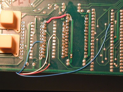
This photo shows the connection points for four of the wires that connect to the memory board. The larger red wire is left-over from the previous version of the mod, and would not be needed when using the memory board. Note that the fifth wire connects on the top side of the Max main board.
Here is a list of the parts required to perform the modification, and their approximate cost.
Here are instructions for performing the modification. Note: Please DO NOT attempt this mod if you do not already have decent soldering skills. This is not a good project for learning how to solder. There are lots of connections to be soldered when assembling the memory board and connecting the wires. Sloppy work or poorly soldered joints will cause the upgrade to fail and your Max won't work when you finish. If you don't have the skills to do this mod neatly and correctly, please do not attempt it. Maybe you can find a friend to do it for you?
Here are some technical details on the modification:
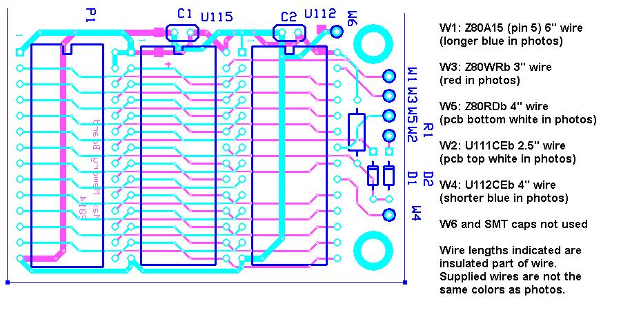
Here is a diagram that shows the wire connection points on the memory board and associated wire lengths.
Here is a schematic of the memory
board. The custom chip used in the Max (and the Multi-Trak)
decodes three 16K regions of the Z80 address space:
A15 A14
0 0 ROM0b active
(EPROM)
0 1 RAM0b active
(U112)
1 0 RAM1b active
(U111)
1 1 Possibly part of the decode for the E signal. This area is used by the 68B50
These decodes drive the chip select inputs of the EPROM and the two RAM chips. The original 27128 EPROM uses all of its 16K space, but the 2Kx8 RAM chips only use 1/8 of their space in the original Max design. The memory board connects the NVRAM to the chip select that was used for U112. The NVRAM is a 32K-byte part, but we can only address half of it using this chip select, without additional circuitry. (You can see that A14 of this chip is simply tied low). For the code additions, we needed to increase the amount of EPROM space available, so we use a larger 27C256 EPROM, and OR the first and third 16K address decodes using diodes to generate a 32K address decode. We use the Z80's A15 line as the upper address to the EPROM, as it is low for the first decode and high for the third one. (A14 wouldn't work, as it's low for both of them) All of the actual code fits in the low half of the 27C256. This is possible because we moved the factory sounds out of that space. The upper half of the EPROM contains the three different sets of factory programs, and the two Max demo songs. As a result, it's possible to simply upgrade the RAM and use a 27128 EPROM and still get the code changes, but without the factory sounds or the demo songs. I don't suggest this, since it's easy at that point to increase the EPROM size as well.
MAX/SixTrak MIDI CC Bug:
Please check my SixTrak page which has more information about this bug.
Here is an archive which contains V05 of the MAX code with the one-byte change to fix the bug.